Current-sharing backlight driving circuit for light-emitting diodes and method for operating the same

a technology of backlight driving circuit and light-emitting diodes, which is applied in the direction of lighting apparatus, electroluminescent light sources, light sources, etc., can solve the problems of increasing the cost of half-bridge or full-bridge structures of converters, affecting the efficiency of led lamps, and not exactly identical current flows through led lamps

Inactive Publication Date: 2012-10-25
DELTA ELECTRONICS INC
View PDF3 Cites 6 Cited by
  • Summary
  • Abstract
  • Description
  • Claims
  • Application Information

AI Technical Summary

Benefits of technology

[0014]Therefore, the class-E converter is provided to produce the AC output voltage and the AC output voltage is converted into the DC driven voltage through the power processing units, thus driving the light-emitting diodes and providing a current-sharing backlight operation.

Problems solved by technology

However, the current flows through the LEDs of the LED lamp may not exactly identical due to somewhat different inner resistances of the LEDs when the LED lamp is driven through a voltage source.
In addition, because the illuminating brightness of each LED is proportional to the forward current thereof, the above-mentioned problem would cause different illuminating brightness, thus overall efficiency of the LED lamp would decrease.
Accordingly, this causes more costs for the half-bridge or full-bridge structure of the converter and causes less reliability problems.

Method used


Image

  • Current-sharing backlight driving circuit for light-emitting diodes and method for operating the same
  • Current-sharing backlight driving circuit for light-emitting diodes and method for operating the same
  • Current-sharing backlight driving circuit for light-emitting diodes and method for operating the same

Examples


Embodiment Construction

[0025]Reference will now be made to the drawing figures to describe the present invention in detail.

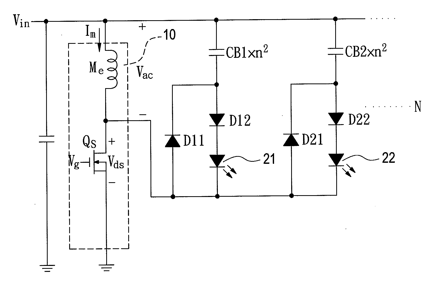
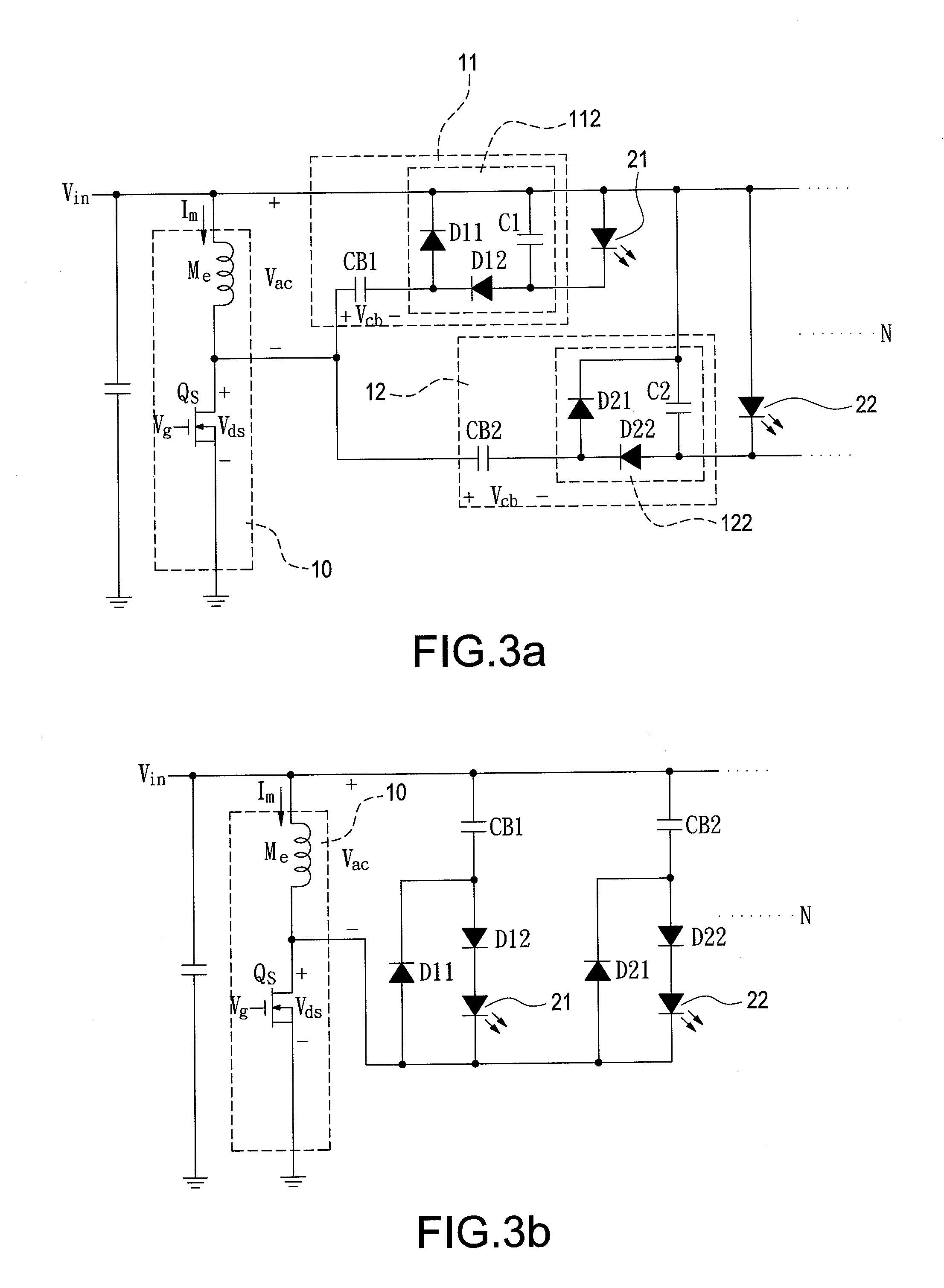
[0026]Reference is made to FIG. 3a which is a circuit diagram of a current-sharing backlight driving circuit for light-emitting diodes according to a first embodiment of the present invention. The current-sharing backlight driving circuit is provided to drive a plurality of light-emitting diodes. In this embodiment, the amount of the current-sharing backlight driving circuit is, but not limited to, two. That is, the current-sharing backlight driving circuit is provided to drive two light-emitting diodes, namely, a first light-emitting diode 21 and a second light-emitting diode 22, respectively. The current-sharing backlight driving circuit includes a class-E converter 10 and a plurality of power processing units. As mentioned above, the current-sharing backlight driving circuit includes two power processing units, namely, a first power processing unit 11 and a second power processing ...


PUM


Abstract

A current-sharing backlight driving circuit for light-emitting diodes and a method for operating the same are disclosed. The current-sharing backlight driving circuit includes a class-E converter and a plurality of power processing units. The class-E converter receives a DC input voltage and produces an AC output voltage. The AC output voltage outputted from the class-E converter is converted into a DC driven voltage thorough the power processing units, thus driving the light-emitting diodes and providing a current-sharing backlight operation.

Description

BACKGROUND OF THE INVENTION[0001]1. Field of the Invention[0002]The present invention relates generally to a current-sharing backlight driving circuit and a method for operating the same, and more particularly to a current-sharing backlight driving circuit for light-emitting diodes and a method for operating the same.[0003]2. Description of Prior Art[0004]For many years, the light-emitting diodes (LEDs) play an important role in the backlight of portable electronic products. In the lighting application, LEDs are the most crucial components in the solid-state lighting industry. The advantages of LEDs include: energy saving, long life-span, free of maintenance, long life-span, and so on. In addition, a well-matched driving circuit for driving LEDs is very necessary in whether the lighting, the backlight, or the display fields. Especially to deserve to be mentioned, the backlight module is an important apparatus for the flat panel display. The backlight module determines the display qu...

Claims


Application Information

Patent Timeline
Patent Type & Authority Applications(United States)
IPC IPC(8): H05B37/02
CPCH05B33/0827H05B45/46
Inventor CHANG, SHIH-HSIENKO, PO-NIEN
Owner DELTA ELECTRONICS INC
Why Eureka
Try Eureka