
Dual action seat release mechanism

a release mechanism and seat technology, applied in the field of seats in vehicles, can solve the problem of limited access to the lever on one side of the seat, and achieve the effect of less complexity in manufacturing and maintaining and low cos

Inactive Publication Date: 2009-05-12
TOYOTA MOTOR CO LTD
View PDF7 Cites 6 Cited by
  • Summary
  • Abstract
  • Description
  • Claims
  • Application Information

AI Technical Summary

Benefits of technology

[0008]One advantage of the present invention is that a dual action seat release mechanism is provided that allows for one-touch operation of a seat back. Another advantage of the present invention is that one-touch operation of the seat back is provided regardless of seat back initial position. Still another advantage of the present invention is that the lever provides for ergonomic operation of the multi-positional seat back. A further advantage of the present invention is that the operation of the seat back is intuitive, since the direction of rotation of the lever is the same as the desired rotation of the seat back. A further advantage of the present invention is that the seat back release lever is accessible from either side of the seat. Still a further advantage of the present invention is that the seat assembly has fewer components, resulting in lower cost and less complexity to manufacture and maintain.

Problems solved by technology

Another feature of both of these systems is that access to the lever is limited to one side of the seat.

Method used


Image

  • Dual action seat release mechanism
  • Dual action seat release mechanism
  • Dual action seat release mechanism

Examples


Embodiment Construction

)

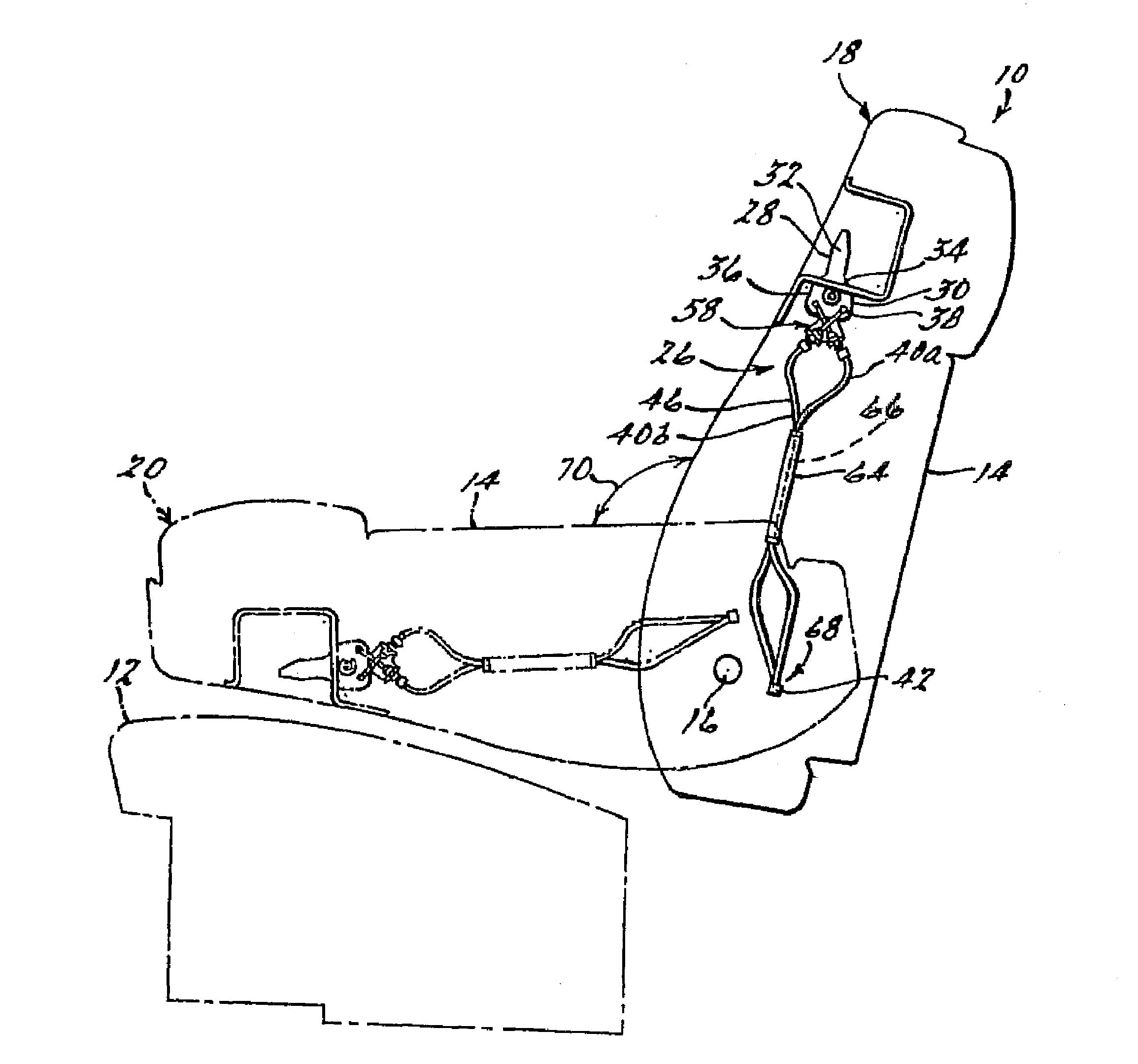
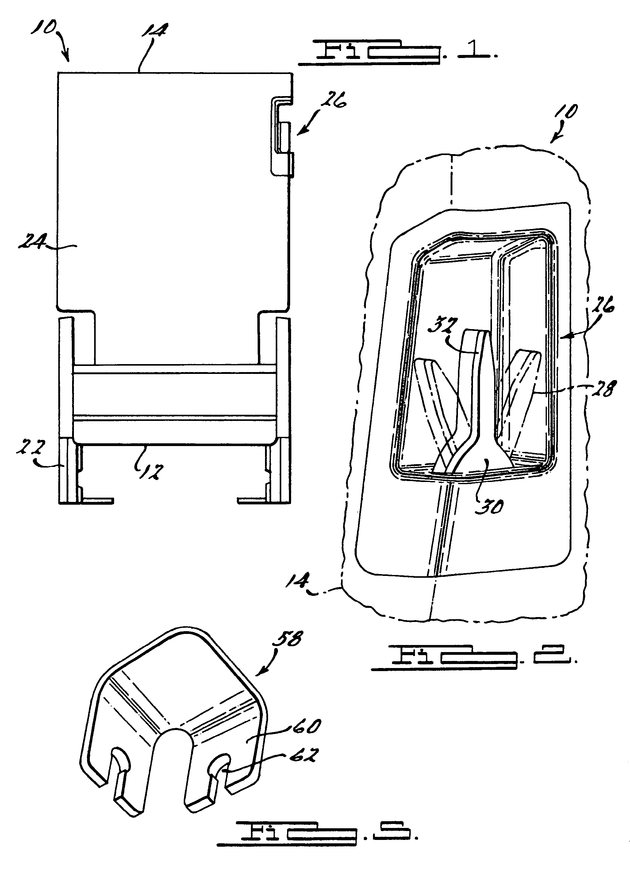
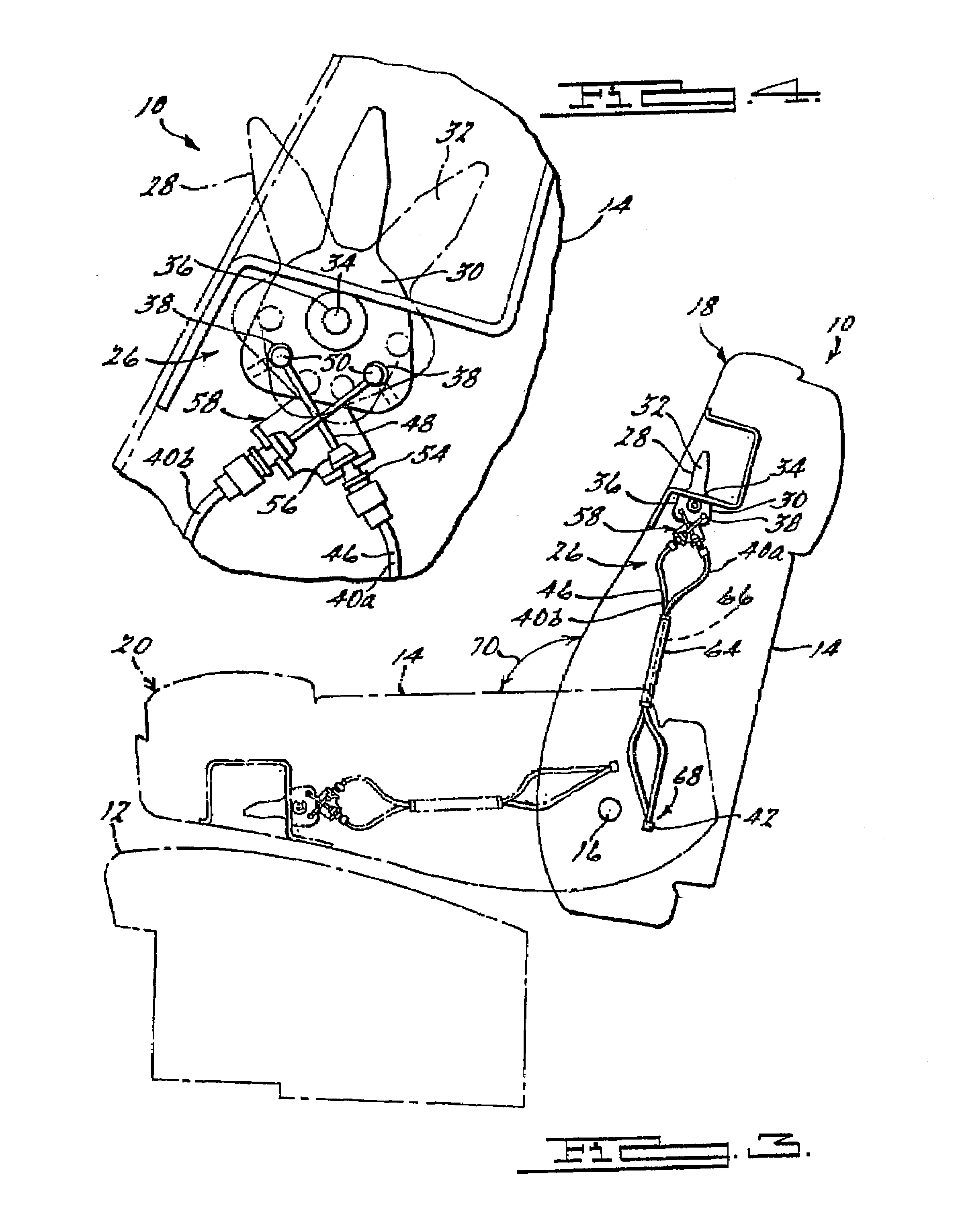
[0015]Referring to FIGS. 1-5, a dual action seat release mechanism for a seat assembly is provided. The seat assembly 10 is utilized within a vehicle, such as an automotive vehicle.

[0016]The seat assembly 10 includes a generally horizontal seat cushion portion 12 and a generally vertically oriented seat back portion 14, which is pivotally connected by a suitable means to the seat cushion portion 12 at a seat back pivot axis, as shown at 16. It should be appreciated that the seat assembly 10 is multi-positional. An upright position of the seat back is illustrated in FIG. 4 at 18, and a folded down position of the seat back is illustrated in FIG. 3 at 20. The seat assembly 10 may include various other features. For example, the seat assembly 10 may be further unlatched from the vehicle to “tumble” forward. The seat assembly 10 may also be removable from the vehicle. The seat assembly 10 may fold flat into the floor of the vehicle. These features of the seat advantageously enhance the...


PUM


Abstract

A dual action seat release mechanism for a seat on a vehicle includes a seat assembly having a vertically oriented seat back portion pivotally connected to a horizontally oriented seat cushion portion. A lever is pivotally attached to the seat assembly, and includes an elongated handle extending from a disc-shaped portion, and a center of the disc-shaped portion is pivotally attached to the seat assembly. A cable attachment means is disposed on the disc-shaped portion of the lever, and is positioned radially outboard from the center of the disc-shaped portion. A cable having a first end and a second end is provided and the first end of the cable is attached to the cable attachment means on the lever. A cable support bracket for fixedly supporting the cable is fixedly attached to the seat assembly. A cable routing bracket for routing the cable is fixedly attached to the seat assembly, and includes an elongated channel for receiving the cable. A seat back release mechanism for unlocking the seat back from the seat cushion portion of the seat is provided, and a second end of the cable is operatively attached to the seat back release mechanism, such that rotation of the lever in a first direction releases the seat back release mechanism for rotation of the seat back in the first direction of rotation, and rotation of the lever in a second direction releases the seat back release mechanism for rotation of the seat back in the second direction of rotation.

Description

BACKGROUND OF THE INVENTION[0001]1. Field of the Invention[0002]The present invention relates generally to seats in vehicles, and more specifically, to a dual action release mechanism for a seat.[0003]2. Description of the Related Art[0004]Vehicles, such as motor vehicles, frequently include seats that are multi-positional. The seat assembly includes a horizontally oriented seat cushion portion connected to a vertically oriented seat back portion. The seat back is multi-positional, that is, it can assume various positions, such as an upright position, a folded flat position, or a reclined position. The seat back position is typically controlled by a seat release mechanism. One example of a seat release mechanism is a lever that is actuated by a user to reposition the seat back in a desired manner. Another example of a seat release mechanism is a strap.[0005]Repositioning of the seat back generally requires two separate operations. For example, one operation involves actuating the se...

Claims


Application Information

Patent Timeline
Patent Type & Authority Patents(United States)
IPC IPC(8): B60N2/02
CPCB60N2/0296B60N2/20B60N2205/40
Inventor DAY, ROBERT CHRISTOPHERBHATIA, VIKAS
Owner TOYOTA MOTOR CO LTD
Learn More