Scroll compressor utilizing liquid or vapor injection

a compressor and liquid or vapor injection technology, applied in the field of compressors, can solve the problems of reducing the compressor efficiency, increasing the heat generated during compression of working fluid, etc., and achieve the effect of robust sealing of the passage and increasing the compressor efficiency

Active Publication Date: 2010-01-14
TECUMSEH PROD CO
View PDF51 Cites 10 Cited by
  • Summary
  • Abstract
  • Description
  • Claims
  • Application Information

AI Technical Summary

Benefits of technology

[0008]The present invention provides a scroll compressor that utilizes liquid or vapor injection to cool a working fluid being compressed by an orbiting scroll member and a non-orbiting scroll member, and / or to increase the efficiency of the compressor. An injection fitting is secured to, and extends through, the compressor housing and receives liquid or vapor working fluid from a source external to the compressor. The non-orbiting scroll member may be fixedly mounted with respect to the crankcase of the compressor, and internal passages formed within the crankcase and the non-orbiting scroll member, which are substantially isolated from the suction pressure and discharge pressure chambers of the compressor, are used to convey liquid or vapor working fluid from the injection fitting into intermediate pressure working pockets defined between the scroll members. The compressor may include an end cap fitted over an open end of its housing which overlaps an end of the passage provided in the non-orbiting scroll member to provide a robust sealing of the passage.

Problems solved by technology

Additionally, when the compressor is undergoing extreme loading, the amount of heat generated during compression of the working fluid rises substantially.
As a result of the rise in temperature of the working fluid, the working fluid expands and the mass flow of the working fluid, i.e., the total mass of working fluid that passes through a portion of the compression mechanism in a given time, is decreased which results in a decrease in the efficiency of the compressor.

Method used


Image

  • Scroll compressor utilizing liquid or vapor injection
  • Scroll compressor utilizing liquid or vapor injection
  • Scroll compressor utilizing liquid or vapor injection

Examples


Embodiment Construction

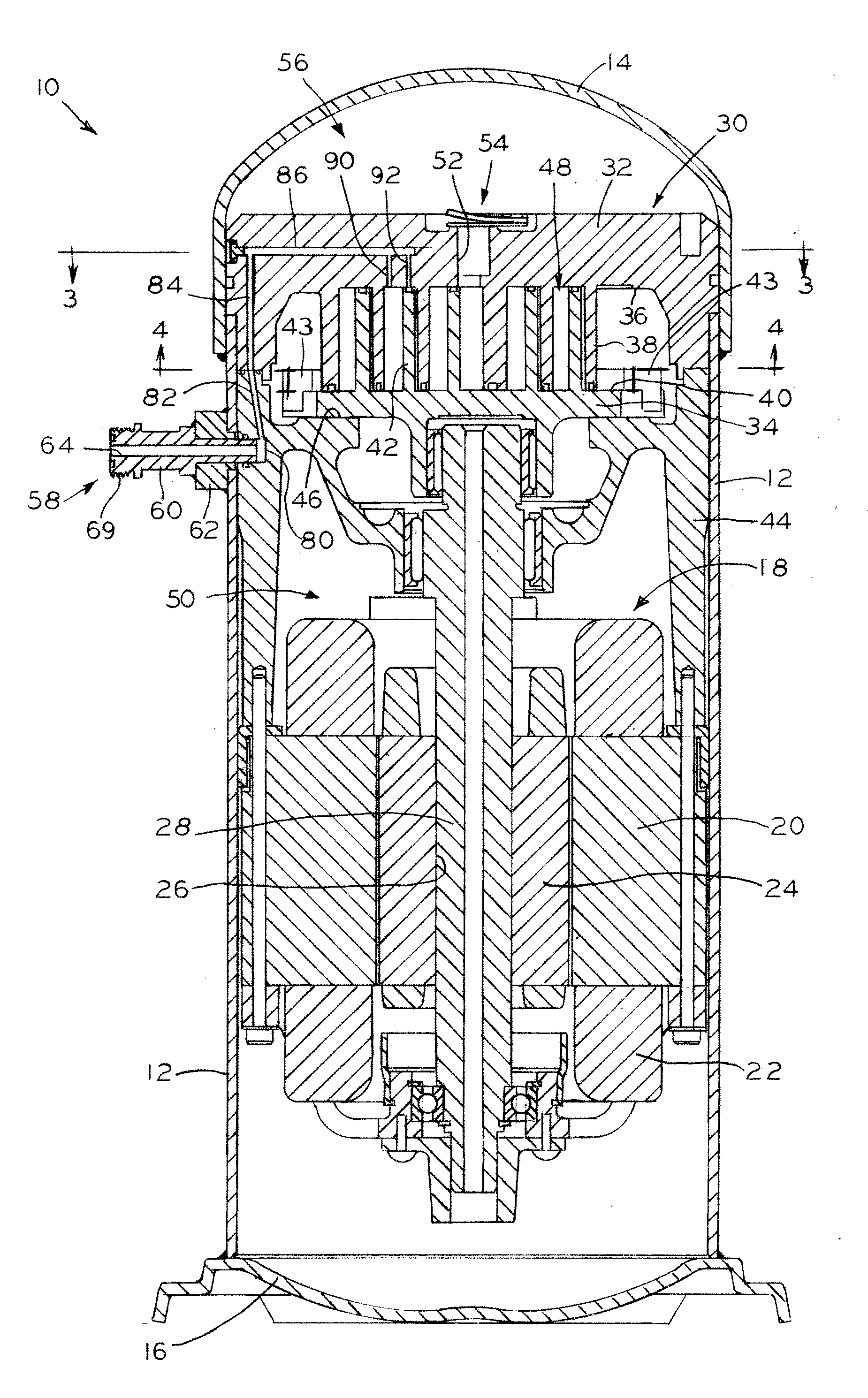
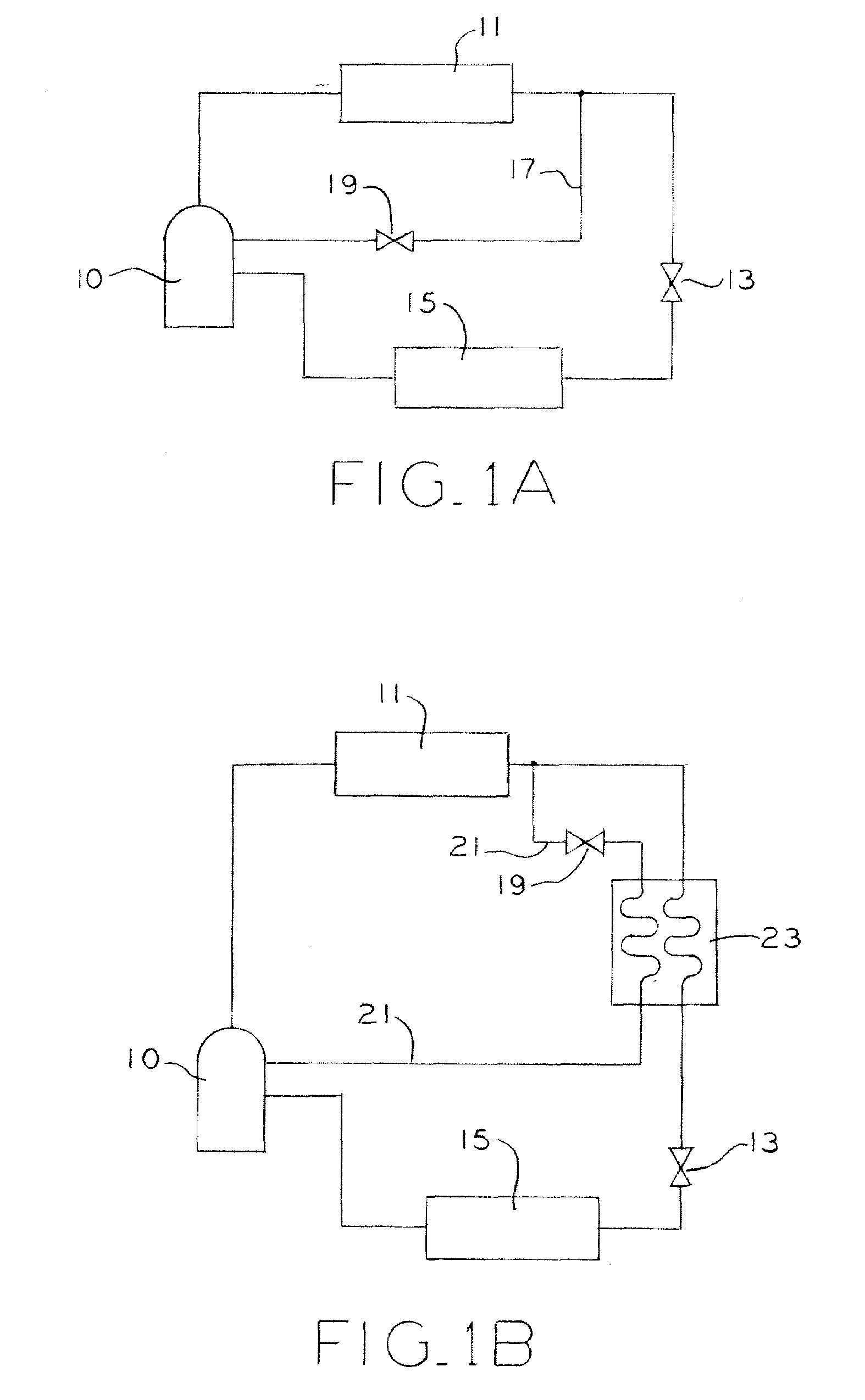
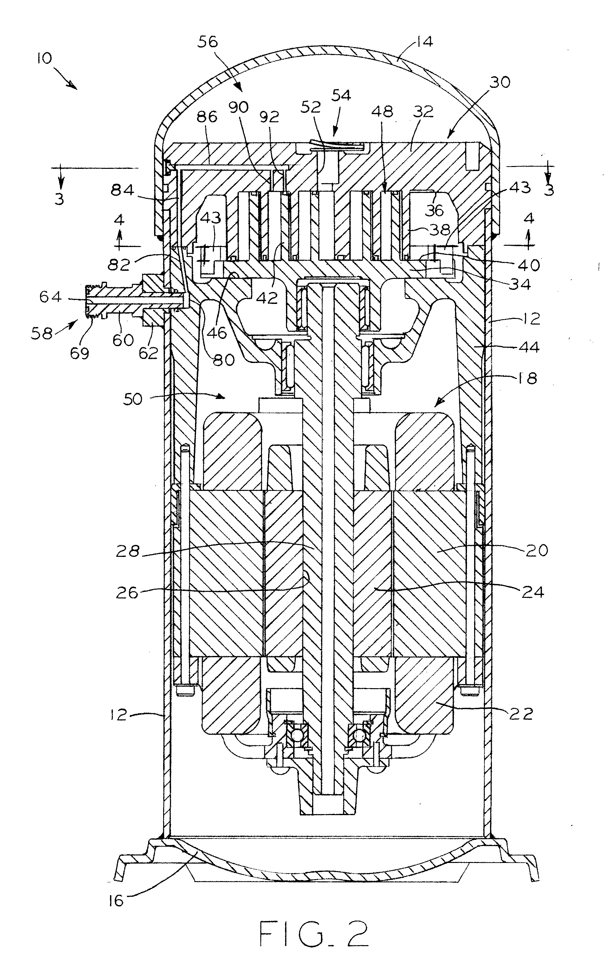
[0027]Referring to FIG. 2, scroll compressor 10 is shown, which may be part of a working fluid circuit, such as the refrigeration circuits shown in FIGS. 1A and 1B in which the working fluid is a refrigerant. Referring to FIGS. 1A and 1B, the refrigeration circuits may each include a condenser 11, an expansion valve 13, and an evaporator 15 connected in series between an outlet and an inlet of compressor 10, as is well known. As will be discussed in further detail below, working fluid, such as refrigerant at an intermediate pressure that is obtained from a suitable location in the refrigeration circuit between the condenser and the evaporator, for example, may be injected into the working pockets defined between the scroll members of the compressor. In the circuit of FIG. 1A, liquid working fluid is obtained via a branch line 17 downstream of condenser 11, and the injection of the liquid working fluid in controlled via a suitable valve 19 in line 17. In the circuit of FIG. 1B, worki...


PUM


Abstract

A scroll compressor that utilizes liquid or vapor injection to cool a working fluid being compressed by an orbiting scroll member and a non-orbiting scroll member, and/or to increase the efficiency of the compressor. An injection fitting is secured to, and extends through, the compressor housing and receives liquid or vapor working fluid from a source external to the compressor. The non-orbiting scroll member may be fixedly mounted with respect to the crankcase of the compressor, and internal passages formed within the crankcase and the non-orbiting scroll member, which are substantially isolated from the suction pressure and discharge pressure chambers of the compressor, are used to convey liquid or vapor working fluid from the injection fitting into intermediate pressure working pockets defined between the scroll members. The compressor may include an end cap fitted over an open end of its housing which overlaps an end of the passage provided in the non-orbiting scroll member to provide a robust sealing of the passage.

Description

CROSS REFERENCE TO RELATED APPLICATIONS[0001]This application claims the benefit under title 35, U.S.C. §119(e) of U.S. Provisional Patent Application Ser. No. 61 / 078,958, entitled COMPRESSOR UTILIZING LIQUID INJECTION, filed on Jul. 8, 2008, the disclosure of which is expressly incorporated by reference herein.BACKGROUND OF THE INVENTION[0002]1. Field of the Invention[0003]The present invention relates to compressors and, in particular, to scroll compressors.[0004]2. Description of the Related Art[0005]In a typical scroll compressor, a motor and a compression mechanism are mounted within a hermetic housing. The compression mechanism includes a non-orbiting scroll member and an orbiting scroll member each having involute wraps in meshing engagement with one another. The orbiting scroll member is supported by a crankcase and driven by the motor. Specifically, the motor drives the crankshaft that, in turn, drives the orbiting scroll. Orbital movement of the orbiting scroll creates a s...

Claims


Application Information

Patent Timeline
Patent Type & Authority Applications(United States)
IPC IPC(8): F01C1/02
CPCF04C18/0215F04C29/042F04C23/008
Inventor ROOF, JOHNATHAN P.GOPINATHAN, ANILSINGH, DAMANJIT
Owner TECUMSEH PROD CO
Why Eureka
Try Eureka