Surface treating head

a surface treatment head and head technology, applied in the direction of suction hoses, cleaning equipment, suction nozzles, etc., can solve the problems of affecting the pick-up performance, affecting the sealing, and affecting the mobility of the surface treatment head, so as to improve the mobility of the surface treatment, improve the suction, and improve the sealing

Inactive Publication Date: 2016-09-27
DYSON TECH LTD
View PDF12 Cites 5 Cited by
  • Summary
  • Abstract
  • Description
  • Claims
  • Application Information

AI Technical Summary

Benefits of technology

[0007]As a result, the relative positions of the two apertures can be adjusted to provide the surface treating head with an optimum configuration for suction, dirt pick-up and cleaning performance over a variety of floor surfaces. By providing the surface treating head with a bellow seal between the first body and the support body, any relative position between the first body and support body can be selected, and any movement between the two apertures during use can take place without any negative impact on the suction achieved between the surface treating head and a floor surface being cleaned. This may result in an improved surface treating head that can better adapt to provide an advantageous configuration to achieve an optimum cleaning performance on a number of different floor types.
[0008]When the first body and support body are in a first relative position the outer aperture may be above the inner aperture in a vertical direction, and when the first body and support body are in a second relative position, the outer aperture may be below the inner aperture in a vertical direction. As a result, either the inner aperture or the outer aperture can be selected to be closest to, or even in contact with, an area of floor surface being cleaned, as one of the inner or outer aperture may provide a better cleaning performance for a specific floor type.
[0011]The surface treating head may further comprise a user-operated lever that moves the one or more of the first body and the support body from the biased position to the other of the first or second relative positions. This allows the user to easily move the relative positions of the first body and support body against the force of the biasing means out of the biased position. The surface treating head may further comprise a catch for releasably holding one or more of the first body and support body in the other of the first or second relative positions that is not the biasing position. This will allow the first body and support body to be held in position against the force of the biasing means. If the catch is subsequently released the first body and support body would then move back into the biased position.
[0012]The biasing means may bias the support body away from the first body into the second relative position, and an adjacent floor surface may provide a force against the biasing means to move the support body towards the first body into the first relative position. This can allow the support body to move up and down freely in response to a changing floor surface type, which ensures that the outer aperture remains in contact with the floor surface, maintaining an outer seal between the floor surface and the outer aperture whether or not the inner aperture is also in contact with the floor surface. This can act to provide a more robust suction seal between the surface treating head and the floor surface.
[0013]The first body and support body may be able to be positioned in an intermediate relative position between the first and second relative positions during use. This enables the two bodies to adopt a relative position that may provide a better seal with the floor surface than either of the first and second relative positions, which may improve suction and therefore cleaning performance of the surface treating head.
[0016]One or more of the first body and support body may comprise floor engaging wheels. Wheels can be used to improve mobility of the surface treating head over the floor surface and can also be used to ensure a predetermined distance is maintained between an adjacent floor surface and one or more of the first body and support body. This may be particularly beneficial, for example, on a hard floor surface and when the first body may be held above the floor surface by floor engaging wheels within the first body. In that instance, only the outer aperture contacts the floor, and creates a larger outer seal. Alternatively, or in addition, the first body and / or support body may comprise floor engaging wheels that serve to prevent the support body from being drawn towards the floor surface too much by the suction force, which could increase motion resistance.

Problems solved by technology

However, on a hard floor surface, the working edges would slide along the surface of the floor with barely any effect on loosening the dust and dirt to be picked up, and would therefore act to worsen the pick-up performance.
Unfortunately, movable brushes within the surface treating head can give rise to a decrease in suction if air is able to pass through any gaps formed between the brushes and the body of the surface treating head.
Having brushes that move up and down can also disrupt the seal and can reduce the suction generated at the floor surface.

Method used


Image

  • Surface treating head
  • Surface treating head
  • Surface treating head

Examples


Embodiment Construction

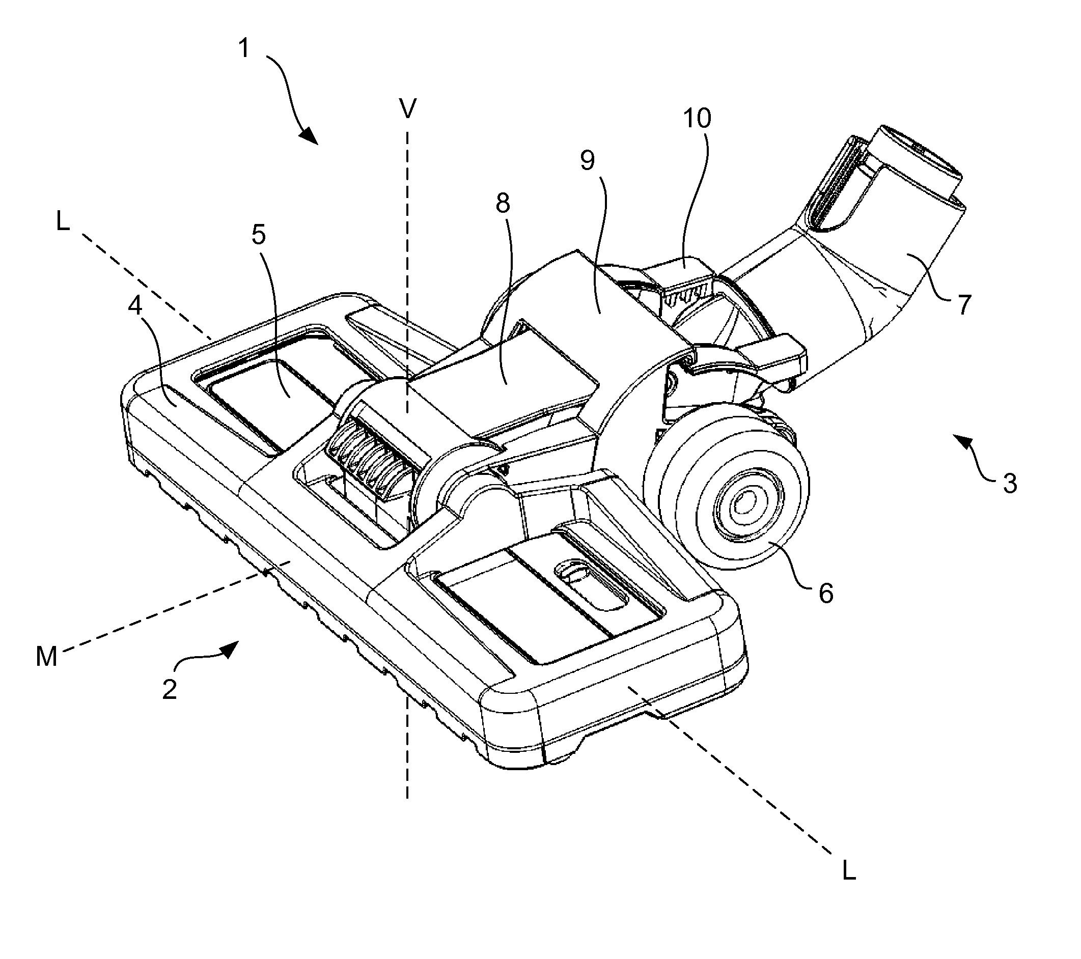
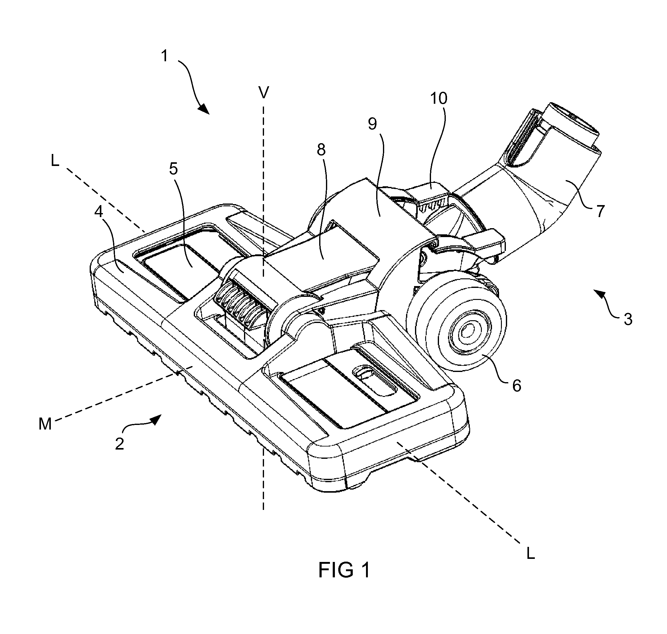
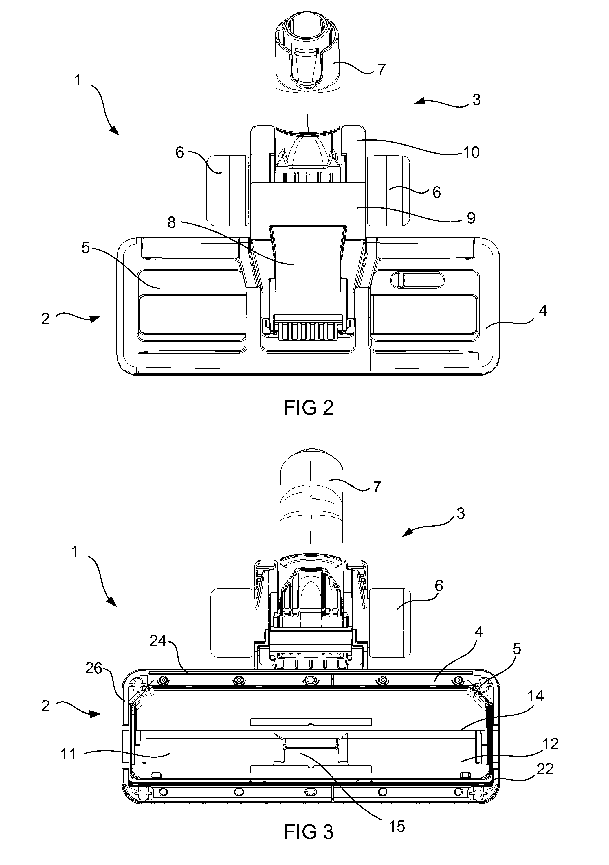
[0027]FIGS. 1, 2 and 3 show a surface treating head 1. The surface treating head 1 comprises a main body 2 and a rolling support 3. The main body 2 comprises a first body which is a soleplate body 5, a support body 4 that surrounds the soleplate body 5. The support body 4 and the soleplate body 5 are moveable relative to one another in a substantially vertical direction, i.e. substantially parallel to axis V. The rolling support 3 comprises wheels 6 and a swivel duct 7. The swivel duct 7 allows the surface treating head 1 to be attached to a vacuum cleaner, for example by way of a wand attachment in the case of a cylinder- or canister-style vacuum cleaner. The swivel duct 7 is in fluid connection with the main body 2, and in particular with the soleplate body 5, by way of duct 8. Lever 9 and catch 10 are provided on the upper side of the surface treating head 1 and which can be used to select and de-select different relative positions of the soleplate body 5 and the support body 4. ...


PUM


Abstract

A surface treating head comprising a first body defining an inner aperture, and a support body defining an outer aperture, the outer aperture surrounding the inner aperture, and the support body being moveable relative to the first body to allow for relative movement between the inner and outer apertures in a substantially vertical direction, wherein the surface treating head further comprises a bellow seal provided between the first body and the support body that maintains a substantially airtight seal between the first body and support body irrespective of their relative positions and movements.

Description

REFERENCE TO RELATED APPLICATIONS[0001]This application claims the priority of United Kingdom Application No. 1405063.7, filed Mar. 21, 2014, the entire contents of which are incorporated herein by reference.FIELD OF THE INVENTION[0002]The present invention relates to a surface treating head.BACKGROUND OF THE INVENTION[0003]Surface treating appliances such as vacuum cleaners are usually provided with one or more surface treating heads, often referred to as a cleaner head. It is common for cleaner heads to be able to be manipulated between different “modes” of use. The different modes can, for example, allow for more effective cleaning by the surface treating head on different types of floor surface, such as carpeted or hard floors.[0004]One example of the different modes that can be provided in a surface treating head is to have a set of brushes that can be raised or lowered with respect to a soleplate. In a raised position, the soleplate may be positioned lower than the brushes, an...

Claims


Application Information

Patent Timeline
Patent Type & Authority Patents(United States)
IPC IPC(8): A47L9/02A47L9/24A47L9/00A47L9/04A47L11/30A47L9/06
CPCA47L9/02A47L9/009A47L9/0477A47L9/0666A47L9/242A47L11/30A47L9/04A47L9/06
Inventor GRAY, JONATHAN JAMESCROSS, SIMON PETER
Owner DYSON TECH LTD
Why Eureka
Try Eureka