Capacitance coupling structure of medium filter

A dielectric filter and capacitive coupling technology, which is applied to waveguide devices, circuits, electrical components, etc., can solve the problems of cumbersome manufacturing process, complex structure, and difficult process realization.

Inactive Publication Date: 2019-05-14
SUZHOU PERFECT ELECTRONICS TECH
View PDF0 Cites 10 Cited by
  • Summary
  • Abstract
  • Description
  • Claims
  • Application Information

AI Technical Summary

Problems solved by technology

At present, the structure of realizing capacitive coupling (or negative coupling) in solid dielectric filters is relatively complicated, the proces...

Method used


Image

  • Capacitance coupling structure of medium filter

Examples


Embodiment Construction

[0012] The specific implementation manners of the present invention will be further described below in conjunction with the drawings and examples. The following examples are only used to illustrate the technical solution of the present invention more clearly, but not to limit the protection scope of the present invention.

[0013] The technical scheme of concrete implementation of the present invention is:

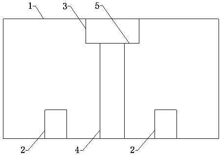
[0014] like figure 1 As shown, a capacitive coupling structure of a dielectric filter includes a dielectric filter body 1 and two blind holes 2 arranged on the surface of the dielectric filter body 1, and each of the blind holes 2 forms a dielectric resonance with the medium filled around it. device, and each of the blind holes 2 is used to debug the resonant frequency of the dielectric resonator; the dielectric filter body 1 is also provided with a negative coupling hole between the two dielectric resonators, the negative coupling The hole is used to realize the capacit...


PUM


Abstract

The invention discloses a capacitance coupling structure of a medium filter. The capacitance coupling structure comprises a medium filter body and two blind holes, wherein the two blind holes are formed in a surface of the medium filter body, each blind hole and a medium filled around each blind hole form a medium resonator, each blind hole is used for debugging a resonant frequency of the mediumresonator, a negative coupling hole is formed in the medium filter body and is arranged between the two medium filters, the negative coupling hole is used for achieving capacitance coupling between the two medium resonators, the negative coupling hole comprises a first through hole and a second through hole which are sequentially arranged from top to bottom, an upper end of the first through holepenetrates through an upper surface of the medium filter body, a lower end of the first through hole communicates with an upper end of the second through hole, a lower end of the second through hole penetrates through a lower surface of the medium filter body, and a conductive layer is plated on an inner wall of the second through hole. The capacitance coupling structure of the medium filter is reasonable in structure, is easy to process, form and surface-processed and is beneficial for weight reduction of the filter.

Description

technical field [0001] The invention relates to a capacitive coupling structure of a dielectric filter. Background technique [0002] Modern communication systems require higher and higher filter volumes, and the advantages of dielectric filters in terms of performance and volume are becoming more and more obvious. At present, the structure of realizing capacitive coupling (or negative coupling) in solid dielectric filters is relatively complicated, the process is difficult to realize, and the manufacturing process is relatively cumbersome, which is not conducive to reducing manufacturing costs for enterprises. Contents of the invention [0003] The purpose of the present invention is to provide a capacitive coupling structure of a dielectric filter, which has a reasonable structure, is easy to process and shape and surface treatment, and is beneficial to reduce the weight of the filter. [0004] To achieve the above object, the technical solution of the present invention...

Claims


Application Information

Patent Timeline
IPC IPC(8): H01P1/20
Inventor 朱亮张剑
Owner SUZHOU PERFECT ELECTRONICS TECH
Why Eureka
Try Eureka