Method for producing an apparatus for dispensing a medium

a technology for producing apparatuses and mediums, applied in the field of producing apparatuses for dispensing mediums, can solve the problems of affecting the quality and accuracy of dispensing, and sometimes too costly solutions for certain, so as to increase the reliability and accuracy of the dispensing process, reduce the gas volume, and reduce the effect of gas leakag

Active Publication Date: 2017-09-21
SULZER MIXPAC AG
View PDF8 Cites 3 Cited by
  • Summary
  • Abstract
  • Description
  • Claims
  • Application Information

AI Technical Summary

Benefits of technology

[0041]This structure has inter alia the advantage that the conveying side of the piston and the outlet face of the cartridge cover are formed such that they have substantially matching shapes. Since the unwanted gas is usually trapped between the conveying side of the piston and the outlet face of the cartridge cover, the residual volume for the gas can be minimized; this can increase the reliability and accuracy of the dispensing process.
[0042]Usually, a lip seal is arranged circumferentially at a side wall of the piston. The lip seal is used to provide a fluid-tight sealing between the piston and an inner wall of the cartridge body. To ensure a fluid-tight sealing, such a lip seal has a certain flexibility of movement to be deflected. To allow for such flexibility, a piston-recess is formed between the side of the lip seal facing the outlet face and the side wall of the piston. A protrusion arranged on the outlet face can reliably engage the piston-recess. The protrusion and the lip seal are producible in a cost efficient manner by molding. Often, the protrusion can be formed as a ring or ridge engaging a ring-like piston-recess of the cylinder-like piston. In a preferred embodiment, the cartridge body is formed substantially as a tube at least in the section of the cartridge in which the piston is movably receivable.
[0043]In a preferred embodiment, the cartridge cover, the piston and the cartridge body are formed by molding in the same mold of the same molding device. This process allows for an even more cost efficient production process while minimizing the residual volume for gas to be trapped. In addition, the assembly of the apparatus can be reliably conducted while minimizing the risk for damaging the seal when inserting the piston into the cartridge, which is sometimes a problem in the state of the art.

Problems solved by technology

The trapped air can be detrimental inter alia to the dispensing quality and accuracy.
Although the known solutions for venting trapped air work reliably and effectively, these solutions are sometimes too costly for certain, cost-critical applications.
Furthermore, the presence of the venting mechanism sometimes provides a residual volume for air to be trapped, which cannot be removed after the filling.
This has the disadvantage of making the filling process more cumbersome and costly.
Moreover, the step of inserting the piston into the cartridge is critical with regard to damaging the piston's sealing lip if not done properly, which can finally result in a leaky apparatus.
The piston is frequently made from a material that has a higher melting temperature than the cartridge body and / or the cartridge cover, so that producing the piston as a first part ensures that the cartridge cover and / or the cartridge body are not permanently bonded to the piston on selection of these materials, or worse, become defective during the molding procedure.
In addition, the assembly of the apparatus can be reliably conducted while minimizing the risk for damaging the seal when inserting the piston into the cartridge, which is sometimes a problem in the state of the art.
Further, the creation of a permanent bond between the cartridge cover and the cartridge body is often required.

Method used


Image

  • Method for producing an apparatus for dispensing a medium
  • Method for producing an apparatus for dispensing a medium
  • Method for producing an apparatus for dispensing a medium

Examples


Embodiment Construction

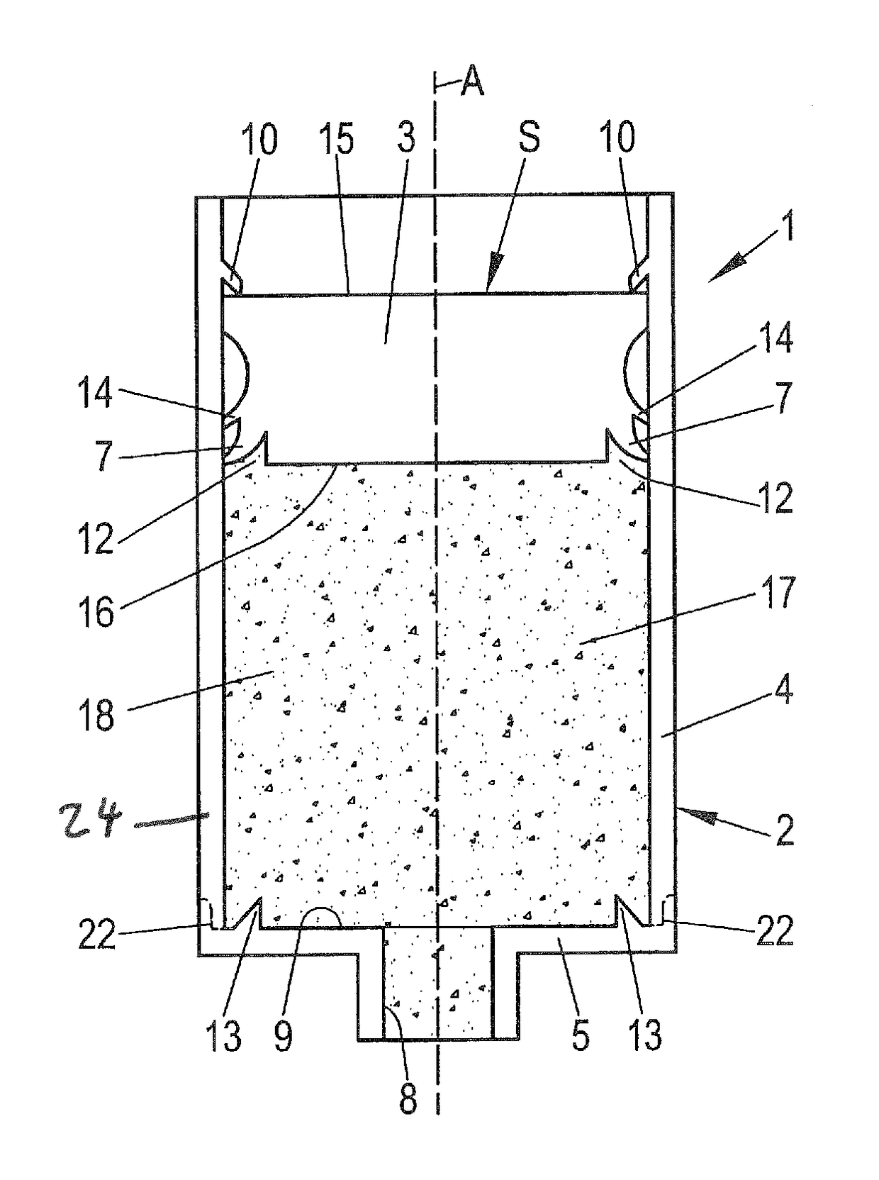
[0073]FIG. 1 shows an apparatus 1 for dispensing a medium 18. The apparatus 1 comprises a cartridge 2, in which a piston 3 is arranged. The piston 3 is movable substantially along a longitudinal axis A of the cartridge 2. The cartridge 2 is formed tube-like at least in the section in which the piston 3 is movably receivable. Further, the cartridge 2 comprises a cartridge housing 24 formed from a cartridge body 4 and a cartridge cover 5.

[0074]The cartridge 2 has blocking means or element 10 arranged in the cartridge 2 at an inner cartridge wall such that the piston 3 cannot be moved accidentally past the blocking element outside the cartridge 2. A protrusion 13 is arranged on the inner surface of the outlet face 9 of the cartridge 2. The protrusion is arranged in a circumferential manner and faces away from the outlet face 9 and is tapered in a direction away from outlet face 9 along the longitudinal axis A of the cartridge 2.

[0075]The cartridge 2 has a storage chamber 17 for receivi...


PUM

PropertyMeasurementUnit
temperatureaaaaaaaaaa
melting temperatureaaaaaaaaaa
polarityaaaaaaaaaa

Abstract

A method is disclosed for producing an apparatus for dispensing a medium. The apparatus includes a cartridge in which a piston is movably receivable. The cartridge includes a cartridge body and a cartridge cover together forming a cartridge housing. The method includes providing a first part in a mold of a molding device, the first part being chosen from at least one of the following parts: cartridge body; piston; cartridge cover. Subsequently, a second part different from the first part is molded in the mold of the molding device, the first part constituting a part of the mold for the second part.

Description

CROSS-REFERENCE TO RELATED APPLICATIONS[0001]This application is a U.S. National Stage application of International Application No. PCT / EP2015 / 069182, filed Aug. 20, 2015, which claims priority to EP Application No. 14181764.3, filed Aug. 21, 2014 the contents of each of which are hereby incorporated herein by reference.BACKGROUND[0002]Field of Invention[0003]The present invention is related to a method for producing an apparatus for dispensing a medium, and to an apparatus produced with the method.[0004]Background Information[0005]It is known in the art to fill a cartridge of such an apparatus by front filling the cartridge through an outlet for dispensing the medium. Alternatively, cartridges are often filled through an inlet arranged on a filling side, which is usually arranged at an end of the cartridge that is arranged opposite to the outlet of the cartridge; this is usually called back filling.[0006]Usually, the cartridge and a piston to be received in the cartridge in a movab...

Claims


Application Information

Patent Timeline
Patent Type & Authority Applications(United States)
IPC IPC(8): B29C45/14
CPCB29C45/14065B29C45/14336B29K2101/12B29K2105/0067B29L2031/712B29C45/16B29C2045/1601B29K2023/06B29K2077/00B29L2031/715
Inventor TURNER, HAYDEN
Owner SULZER MIXPAC AG
Why Eureka
Try Eureka