Non-90-Degree Ergonomically-Shaped Dental Prophylaxis Angle with a Straight Driving Shaft

a driving shaft and non-90-degree technology, applied in dental surgery, dental science, tooth cleaning, etc., can solve the problems of vibration/noise problem, product cost weakness, etc., and achieve the effect of avoiding cross-contamination as well as the expense and inconvenience of sterilization

Inactive Publication Date: 2010-02-11
PAC DENT INT
View PDF39 Cites 14 Cited by
  • Summary
  • Abstract
  • Description
  • Claims
  • Application Information

AI Technical Summary

Benefits of technology

[0006]The invention is directed to a dental prophy angle that has an integrally formed housing, which incorporates two gears (driving gear and driven gear) and a removable prophylaxis head attachment, also called the prophylaxis cup (or “prophy cup”), and which translates rotation from a dental power source to the head attachment through these gears. More specifi...

Problems solved by technology

However, in the present market, those products exhibit cost weakness or vibration/no...

Method used


Image

  • Non-90-Degree Ergonomically-Shaped Dental Prophylaxis Angle with a Straight Driving Shaft
  • Non-90-Degree Ergonomically-Shaped Dental Prophylaxis Angle with a Straight Driving Shaft
  • Non-90-Degree Ergonomically-Shaped Dental Prophylaxis Angle with a Straight Driving Shaft

Examples


Embodiment Construction

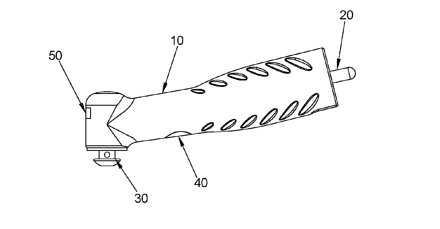
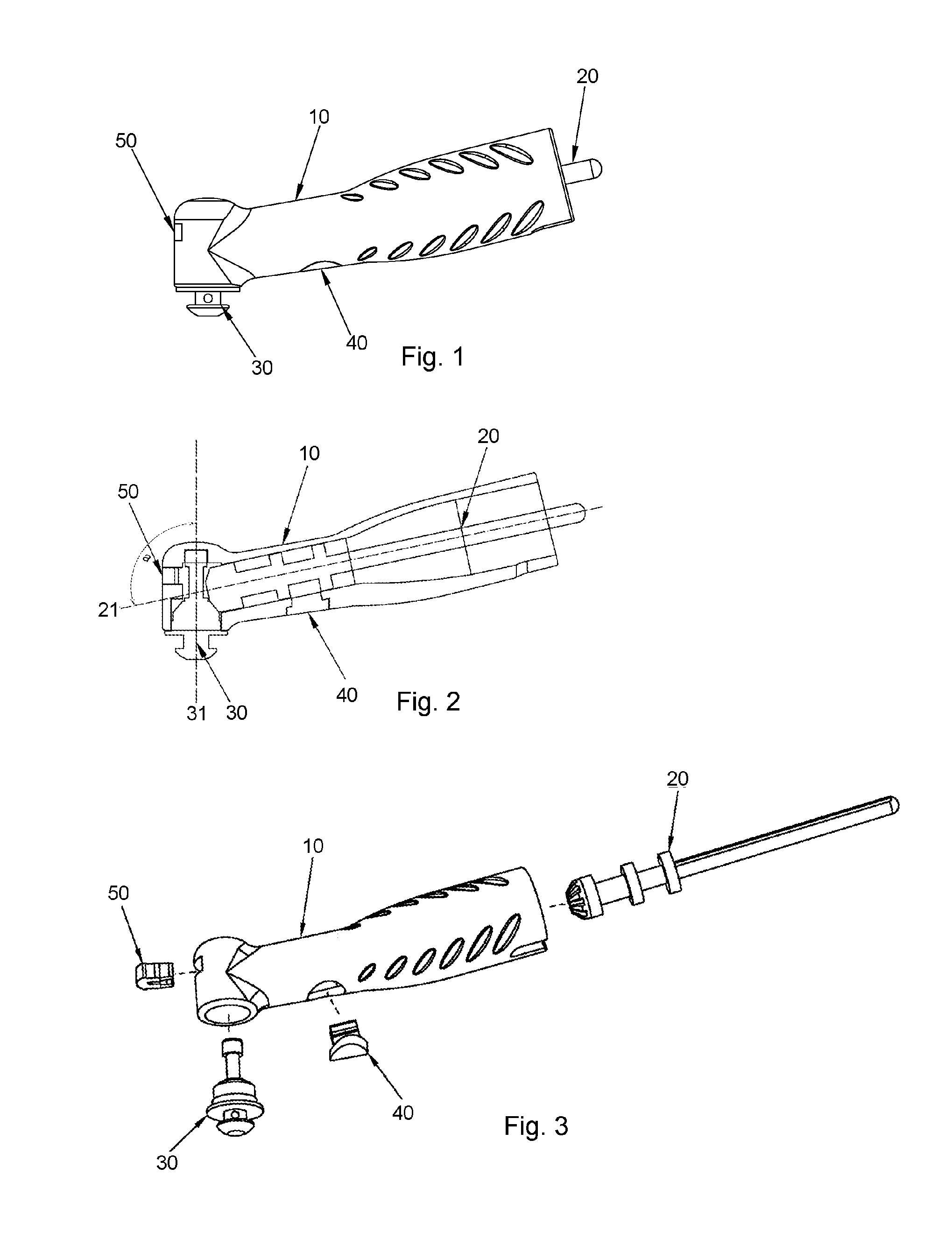
[0021]FIG. 1 and FIG. 2 show perspective and cross-sectional views of one preferred embodiment of the present invention. FIG. 3 shows a perspective view before assembly. The driving shaft 20 and driven rotor 30 are assembled inside of the housing 10 and positioned by the driving locker 40 and the driven retainer 50 correspondingly. The housing consists of a longitudinal tail section and a transverse head section and, as shown in FIG. 2, the angle a between the axis 21 of the driving shaft 20 and the axis 31 of the driven rotor 30 is slightly larger than the 90 degree angle found in most conventional prophy angles on the market. A powered dental handpiece of conventional type (not shown) is coupled to the tail of the driving shaft 20 and a snap-on rubber prophy cup with prophy paste (not shown) is connected to the cup holder head of the driven rotor 30.

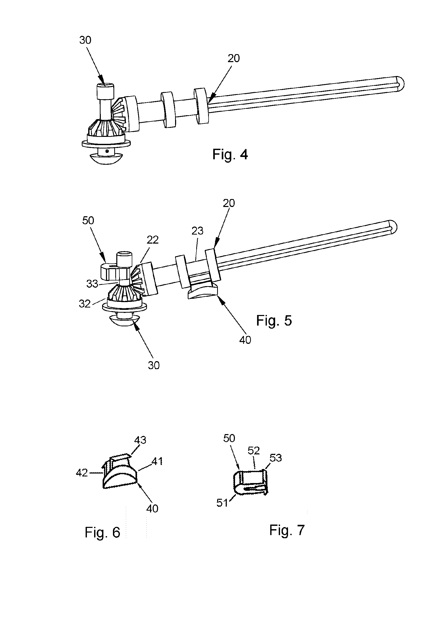
[0022]After assembly, the relative positions of the driving shaft 20 and the driven rotor 30 are shown in FIG. 4. The driving locker ...


PUM


Abstract

A disposable dental angle with a one-piece hollow housing, having the axis of its head section angled obtusely with respect to the axis of its tail section, is provided. The obtusely angled front aperture of the head section of the housing allows insertion of a driven rotor such that the driven rotor is positioned with an obtuse angle to the driving shaft in the end aperture of the tail section of the housing. The obtuse angle structure facilitates teeth cleaning operations by allowing the dental angle to easily reach all areas of the mouth and making practitioners feel more comfortable by allowing to maintain an ergonomically correct neutral wrist position and therefore reducing hand fatigue. A horseshoe-like snap retainer fits within the head section of the housing over the driven rotor to retain the rotor from coming out. A similar horseshoe-like snap retainer fits within the tail section of the housing over the driving shaft to retain the shaft firmly such that the gear of the driven rotor is always properly coupled to the matching gear of the driving shaft. The driving shaft transfers the rotation from a dental tool to the driven rotor for the purpose of tooth prophy using a cleaning cup.

Description

FIELD OF THE INVENTION[0001]The present invention relates to a disposable dental appliance and more particularly to a dental prophylaxis angle (or “prophy angle”) used for cleaning teeth, and more especially to those to be disposed of after each patient to avoid cross infection.BACKGROUND OF THE INVENTION[0002]A conventional prophy angle is used in dental treatment to remove plaque and to polish the surface of the enamel of teeth. A prophy cup is secured to the angle and is rotated by a drive mechanism, typically a gear drive. The prophy cup is shaped to retain a desired amount of prophy paste which is used to clean a patient's teeth.[0003]A typical drive mechanism is a gear connection between a driving gear shaft and a driven gear rotor at a right angle of 90 degrees. The driving shaft is rotated by a dental drive means of a dental tool (such as a dental handpiece) with speeds typically ranging from 2,500 to 4,500 rpm. The rotation is transferred to the driven rotor by the gearing ...

Claims


Application Information

Patent Timeline
IPC IPC(8): A61C1/12
CPCA61C1/12A61C17/005A61C1/185
Inventor WANG, DANIELSHEN, JIANPINGZHU, YONG
Owner PAC DENT INT
Why Eureka
Try Eureka