Composite ceramic electrode, ignition device therewith and methods of construction thereof

a ceramic electrode and composite technology, applied in the field of electrodes therefor, can solve the problems of affecting limiting the material capability of spark plugs, and reducing the useful life of spark plugs

Active Publication Date: 2010-03-04
FEDERAL MOGUL IGNITION
View PDF13 Cites 12 Cited by
  • Summary
  • Abstract
  • Description
  • Claims
  • Application Information

AI Technical Summary

Problems solved by technology

These higher operating temperatures have an adverse affect on the spark plugs by diminishing their useful life.
In particular, the higher temperatures are pushing the spark plug electrodes to the very limits of their material capabilities, and in some cases beyond the limits, thereby resulting in failure of the electrode.
Since combustion environments are highly oxidizing, corrosive wear including deformation and fracture caused by high temperature oxidation and sulfidation can result and is particularly exacerbated at the highest operating temperatures.
At the upper limits of operating temperature (e.g., 1400° F. or higher), tensile, creep rupture and fatigue strength also have been observed to decrease significantly which can result in deformation, cracking and fracture of the electrodes.
Depending on the electrode design, specific operating conditions and other factors, these high temperature phenomena may contribute individually and collectively to undesirable growth of the spark plug gap, which increases the voltage required to cause sparking and diminishes performance of the ignition device and associated engine.
In extreme cases, failure of the electrode, ignition device and associated engine can result from electrode deformation and fracture resulting from these high temperature phenomena.
Further, these electrodes can be very costly to construct.

Method used


Image

  • Composite ceramic electrode, ignition device therewith and methods of construction thereof
  • Composite ceramic electrode, ignition device therewith and methods of construction thereof
  • Composite ceramic electrode, ignition device therewith and methods of construction thereof

Examples


Embodiment Construction

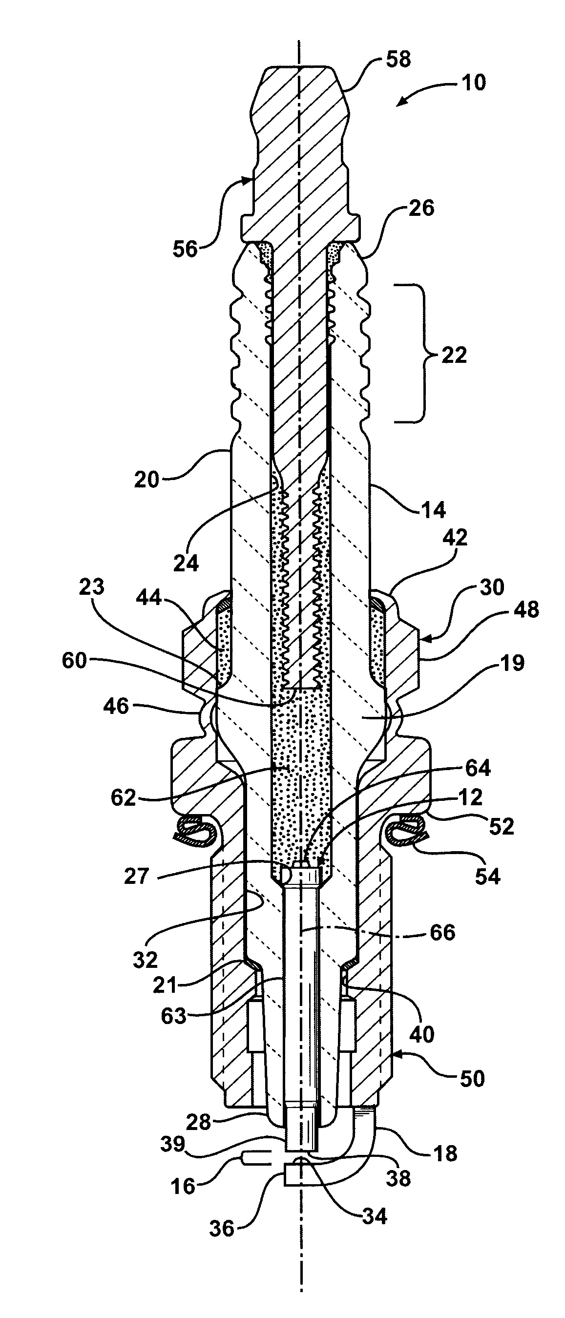
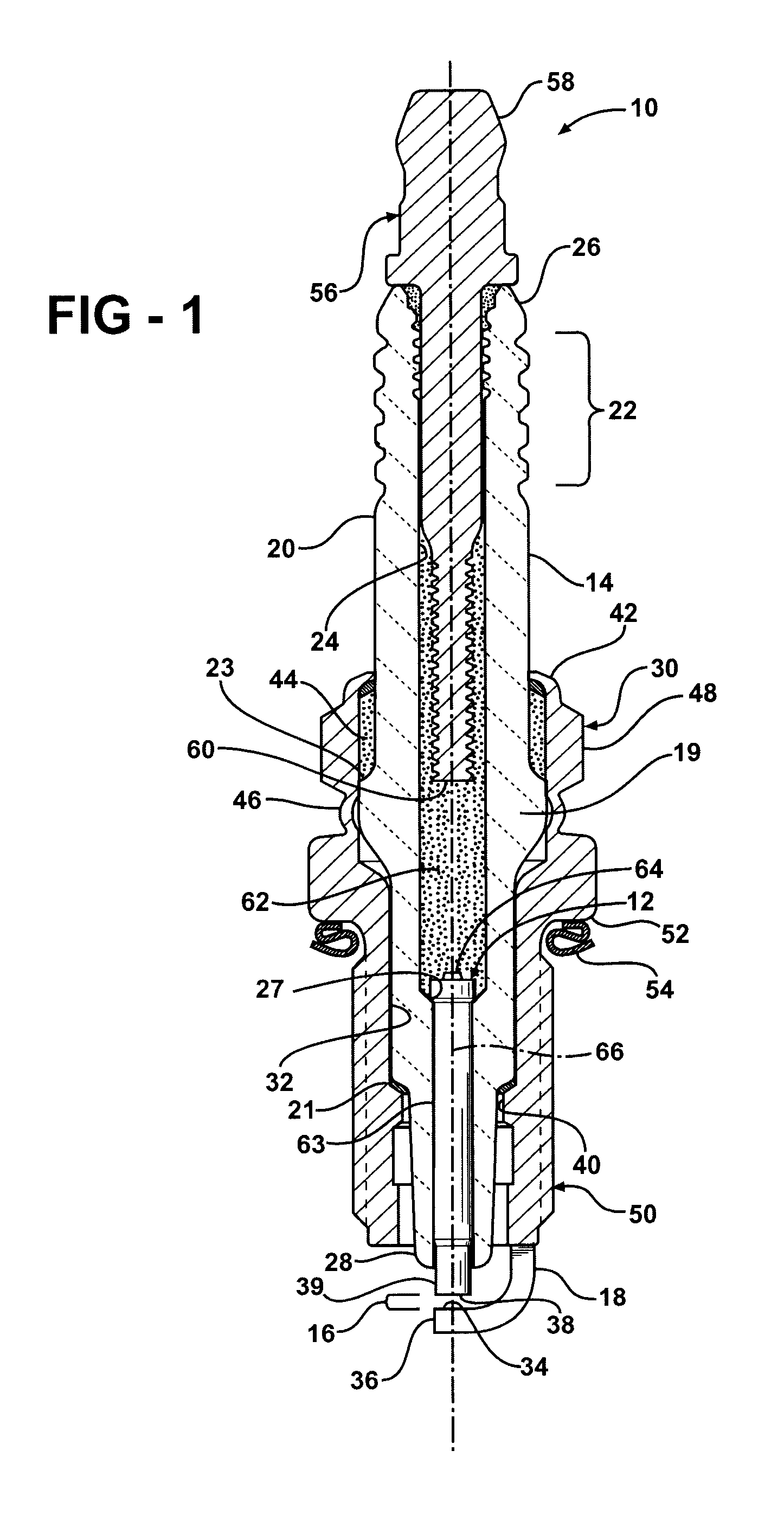
[0020]Referring in more detail to the drawings, FIG. 1 illustrates a spark ignition device, referred to hereafter as spark plug, generally at 10 used for igniting a fuel / air mixture within an internal combustion engine (not shown). The spark plug 10 has a center electrode 12 constructed of a composite ceramic / ceramic material or a composite ceramic / metal material in accordance with the invention. The materials used for the center electrode 12 are capable of withstanding the most extreme temperature, pressure, chemical corrosion and physical erosion conditions experienced by the spark plug 10. These conditions include exposure to numerous high temperature chemical reactant species associated with the combustion process which commonly promote oxidation, sulfidation and other high temperature corrosion processes, such as those attributed to calcium and phosphorus in the combustion products, as well as reaction of the plasma associated with the spark kernel and flame front which promote...


PUM

PropertyMeasurementUnit
widthaaaaaaaaaa
lengthaaaaaaaaaa
concentrationaaaaaaaaaa

Abstract

A spark plug, center electrode and method of construction is provided. The spark plug has a generally annular ceramic insulator and a conductive shell surrounding at least a portion of the ceramic insulator. A ground electrode is operatively attached to the shell, with the ground electrode having a ground electrode sparking surface. A center electrode has an elongate body with a center electrode sparking surface. The center electrode sparking surface and the ground electrode sparking surface provide a spark gap. The center electrode body is constructed of a composite material including at least one ceramic material.

Description

BACKGROUND OF THE INVENTION[0001]1. Field Of The Invention[0002]The invention relates generally to ignition devices for internal combustion engines, and more particularly to electrodes therefor.[0003]2. Related Art[0004]A spark plug is a spark ignition device that extends into the combustion chamber of an internal combustion engine and produces a spark to ignite a mixture of air and fuel. Spark plugs typically have an outer ceramic insulator, which is fabricated and fired separately from other components of the spark plug, a center electrode extending partially through the insulator to a firing tip, and a ground electrode extending from an outer metal shell. A separate resistor component is commonly coupled to an end of the electrode within the insulator opposite the firing end of the electrode. The resistor acts to suppress radio frequency (RF) electromagnetic radiation, which if left unchecked, can affect the transmission of other electrical signals, including inferring with radio...

Claims


Application Information

Patent Timeline
Patent Type & Authority Applications(United States)
IPC IPC(8): H01T13/20H01T21/02
CPCH01T21/02H01T13/39H01T13/20H01T13/34
Inventor WALKER, JR., WILLIAM J.LYKOWSKI, JAMES D.
Owner FEDERAL MOGUL IGNITION
Why Eureka
Try Eureka