Floating lens mounting system

Active Publication Date: 2010-04-08
OAKLEY INC
View PDF55 Cites 194 Cited by
  • Summary
  • Abstract
  • Description
  • Claims
  • Application Information

AI Technical Summary

Benefits of technology

[0011]Despite the long-standing utility of prior art eyewear designs, an aspect of at least one embodiment of the present inventions includes the realization that the lenses of the prior art eyeglasses as mounted provide decreased optical quality at least because the design of the eyeglasses and the method of manufacturing these eyeglasses. In particular, according to at least one of the embodiments disclosed herein is the realization that the geometry of the lenses of prior art eyegl

Problems solved by technology

Distortion may be introduced by any of a variety of influences, such as poor construction materials for the optical portion of the lens and inferior polishing and/or molding techniques for the lens.
In addition, optical distortion can result from the interaction of the lens with the frame, such as changes in the shape of the lens orbital or poor orientation of the lens with respect to the normal line of sight.
Eyeglass systems which use a polymeric or metal wire frame are susceptible to bending and flexing due to a variety of environmental causes such as impact, storage induced and other external forces, forces resulting from the assembly process of the eyewear, and exposure to sunlight and heat.
Flexing of the lens or uncontrolled deviation of the orientation of one lens with respect to the other or with respect to the ear stems can undesirably change the optical characteristics of the eyeglasses, whether the lens is corrective (prescription) or noncorrective.
In particular, according to at least one of the embodiments disclosed herein is the realization that the geometry of the lenses of prior art eyeglasses is distorted or deformed from its original as-molded or pre-mounted geometry when mounted in the eyeglass, thus creating one or more optical aberrati

Method used


Image

  • Floating lens mounting system
  • Floating lens mounting system
  • Floating lens mounting system

Examples


Embodiment Construction

[0088]While the present description sets forth specific details of various embodiments, it will be appreciated that the description is illustrative only and should not be construed in any way as limiting. Additionally, it is contemplated that although particular embodiments of the present inventions may be disclosed or shown in the context of unitary or dual lens eyewear systems, such embodiments can be used in both unitary and dual lens eyewear systems. Further, it is contemplated that although particular embodiments of the present inventions may be disclosed or shown in the context of frames having full orbitals, such embodiments can be used with frames having both full and partial orbitals. Furthermore, various applications of such embodiments and modifications thereto, which may occur to those who are skilled in the art, are also encompassed by the general concepts described herein.

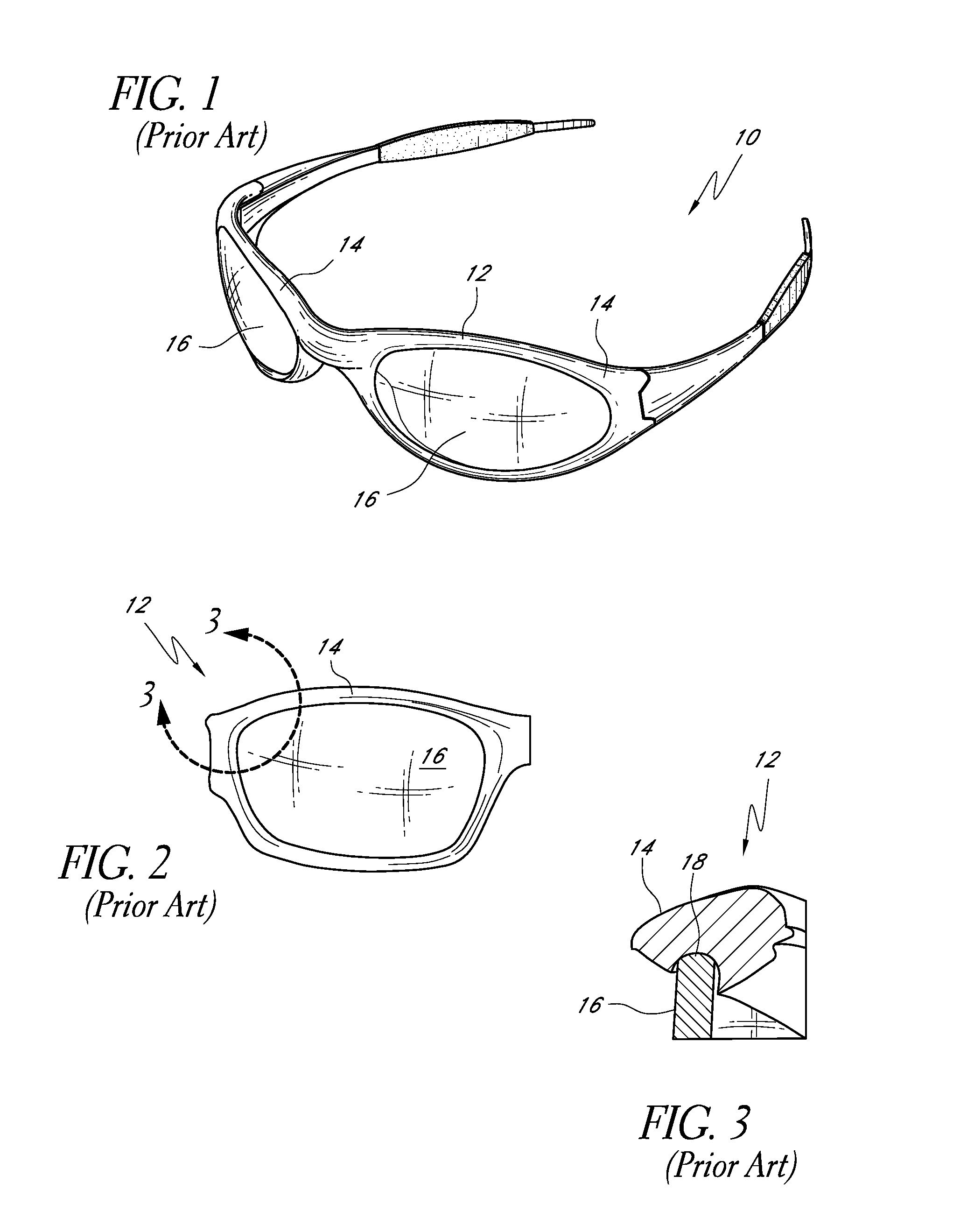
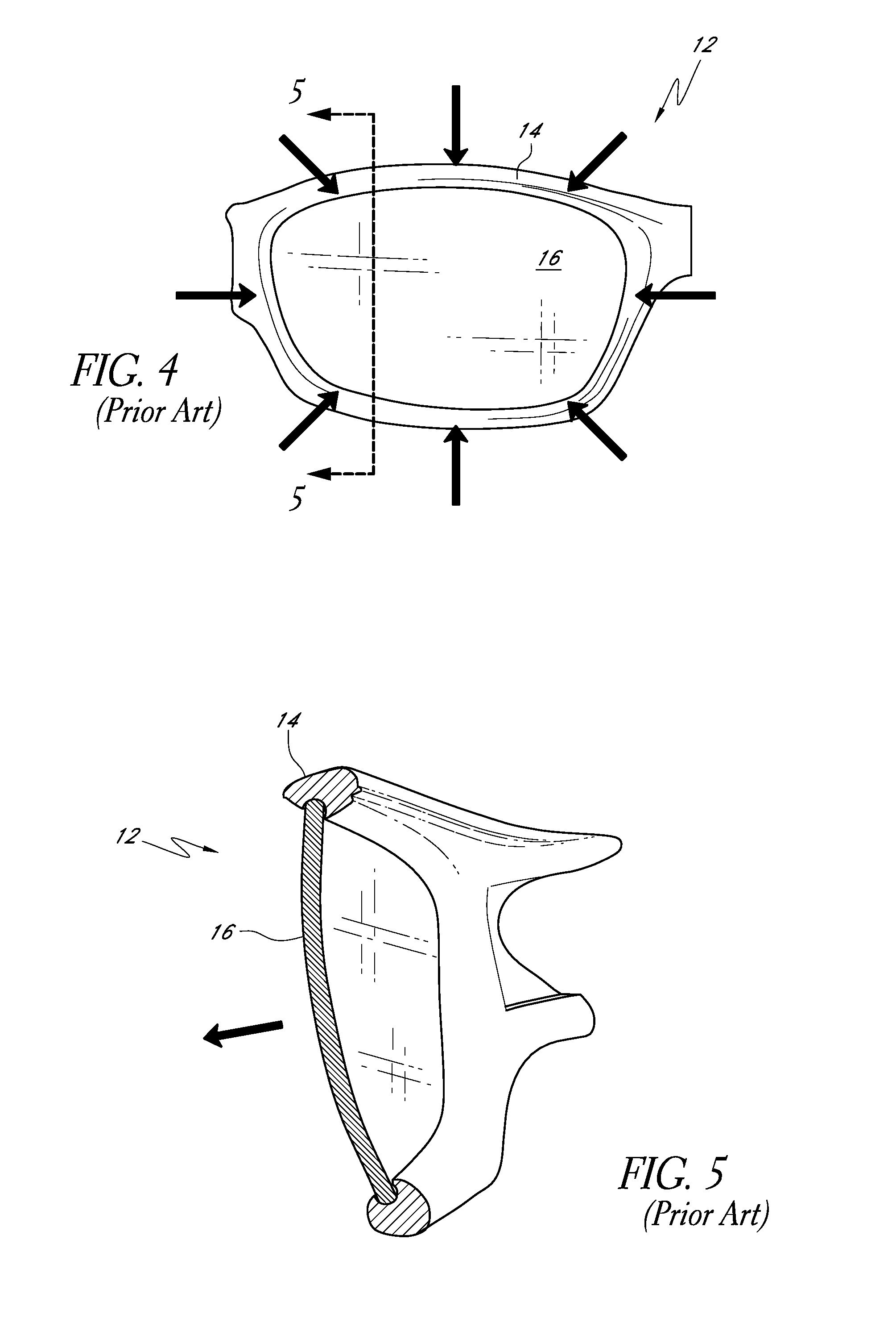
[0089]As discussed above, the prior art eyeglasses illustrated in FIGS. 1-6 have limitations and d...


PUM


Abstract

Various embodiments of an eyeglass and eyeglass system are provided that can maintain the geometric and optical quality of a lens supported by the eyeglass. The eyeglass can comprise a frame, a support member carried by the frame, and a lens mounting area or groove extending at least partially along at least one of the frame and the support member. The support member can be pivoted, moved, or deflected relative to the frame between a retaining position and an open position. In the open position, the lens can be seated within the lens mounting area. In the retaining position, the support member and the frame retain the lens without exerting deformative forces on the lens. Accordingly, the as-molded geometric and optical qualities of the lens can be preserved.

Description

CROSS-REFERENCE TO RELATED APPLICATIONS[0001]This application claims the benefit of U.S. Provisional Application No. 61 / 078,326, filed Jul. 3, 2008, the entirety of which is incorporated herein by reference.BACKGROUND[0002]1. Field of the Inventions[0003]The present inventions relate generally to mounting systems for eyewear. More specifically, the present inventions relate to methods and apparatuses for mounting an optical lens in a manner that maintains the original as-molded or pre-mounted geometry of the lens in order to maintain the geometry and superior optical performance.[0004]2. Description of the Related Art[0005]Various improvements have been made in recent years in the eyewear field. For example, the unitary cylindrical lens was popularized by Blades® (Oakley, Inc.) eyewear which incorporated, among others, the technology of U.S. Pat. No. 4,859,048, issued to Jannard. Toroidal unitary lens geometry having a constant horizontal radius throughout was introduced through a v...

Claims


Application Information

Patent Timeline
IPC IPC(8): G02C1/08G02C1/00G02C5/00
CPCG02C1/06G02C1/08G02C5/008G02C5/12G02C2200/08G02C1/10
Inventor CALILUNG, RYANGINTHER, DAVIDMORITZ, HANSREYES, CARLOSSAYLOR, RYANTRAN, AN
Owner OAKLEY INC
Why Eureka
Try Eureka