Liquid heat capacity lasers

a heat capacity laser and liquid heat technology, applied in the direction of laser cooling arrangements, laser details, active medium materials, etc., can solve the problems of severe limitation of the need to reject a sizable amount of waste heat, etc., to reduce thermal gradients, limit the optical quality of the laser media, and the effect of independent heat capacity run tim

a heat capacity laser and liquid heat technology, applied in the direction of laser cooling arrangements, laser details, active medium materials, etc., can solve the problems of severe limitation of the need to reject a sizable amount of waste heat, etc., to reduce thermal gradients, limit the optical quality of the laser media, and the effect of independent heat capacity run tim

US20050243883A1Inactive Publication Date: 2005-11-03RGT UNIV OF CALIFORNIA

Image

  • Liquid heat capacity lasers
  • Liquid heat capacity lasers
  • Liquid heat capacity lasers

Examples


Embodiment Construction

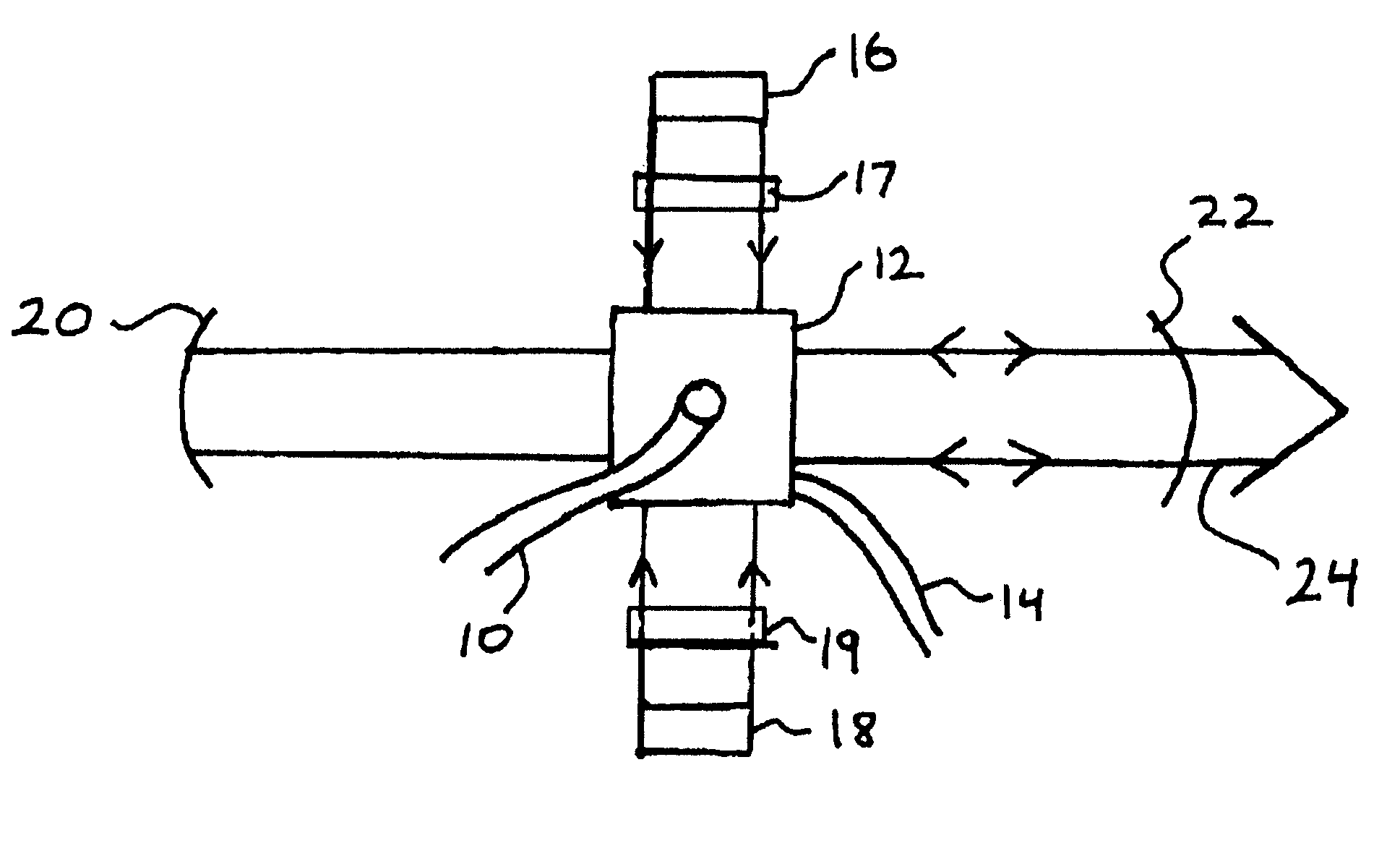
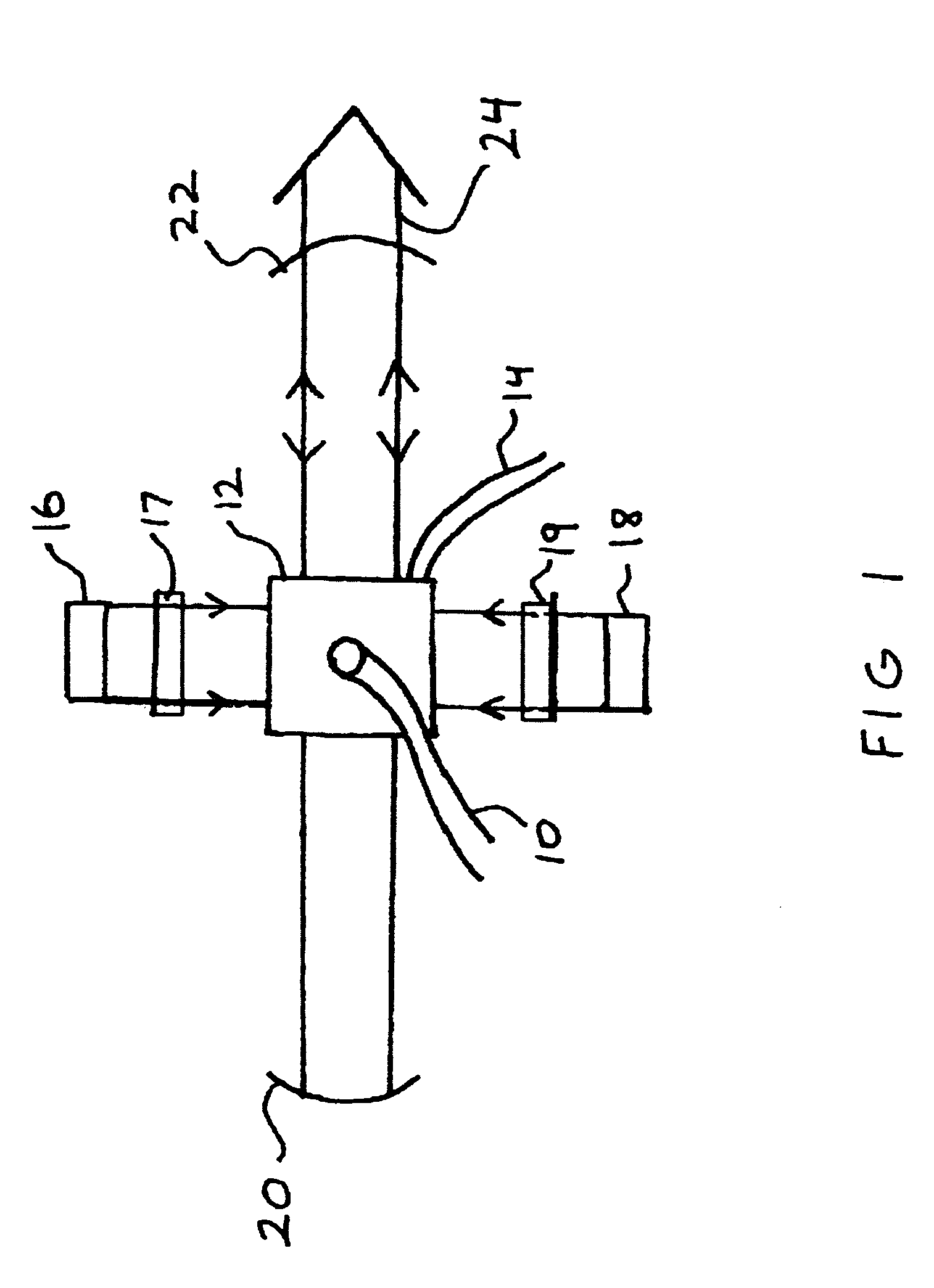
[0017] In the present liquid heat capacity laser, the laser active liquid is circulated from a reservoir (where the bulk of the media and hence waste heat resides) through a channel so configured for both optical pumping of the media for gain and for light amplification from the resulting gain. The pumping is frequently done by (but not exclusively by) arc lamps, flash lamps, and laser diodes. The amplification may occur in the form of a laser oscillator or a laser amplifier. The pumping and lasing processes result in waste heat being deposited in the liquid media and a rise in the reservoir temperature over the run time of the laser. After lasing, the liquid media can be cooled back down to the start temperature at a slower rate than the heating rate by a refrigeration unit consequently smaller and drawing less power than a unit built to maintain the lasing media temperature while lasing. If time permits, even passive cooling could be utilized. For a lasing time of A and a dwell ti...


PUM


Abstract

The heat capacity laser concept is extended to systems in which the heat capacity lasing media is a liquid. The laser active liquid is circulated from a reservoir (where the bulk of the media and hence waste heat resides) through a channel so configured for both optical pumping of the media for gain and for light amplification from the resulting gain.

Description

[0001] The United States Government has rights in this invention pursuant to Contract No. W-7405ENG-48 between the United States Department of Energy and the University of California for the operation of Lawrence Livermore National Laboratory.BACKGROUND OF THE INVENTION [0002] 1. Field of the Invention [0003] The present invention relates to diode pumped heat capacity lasers. More specifically, it relates to the production of high-energy laser output from a liquid state laser operated in a heat capacity limited regime. [0004] 2. Description of Related Art [0005] For continuous operation of medium to high average power lasers various heat exchanger systems, frequently with water flow loops and refrigeration units, have been used to handle the waste heat These cooling systems tend to be a significant (if not dominant) contribution to the laser system's mass, size, and average power consumption. There are a class of laser applications arising today that require minimal mass, volume, an...

Claims


Application Information

Patent Timeline
03 Nov 2005
Publication
US20050243883A1
IPC
H01S3/04; H01S3/0941; H01S3/16; H01S3/20
CPC
H01S3/0402; H01S3/20; H01S3/1611; H01S3/0941
Inventors
COMASKEY, BRIAN J.; SCHEIBNER, KARL F.