Thermal test apparatus and method

a technology of thermal test apparatus and method, which is applied in the direction of material thermal analysis, structural/machine measurement, and material flaw investigation, can solve the problems of air leakage from within the enclosure, and achieve the effect of reducing or negating the effect of reducing the thermal gradient of the specimen, and reducing the weight of the shroud

Inactive Publication Date: 2011-05-19
AIRBUS OPERATIONS LTD
View PDF27 Cites 6 Cited by
  • Summary
  • Abstract
  • Description
  • Claims
  • Application Information

AI Technical Summary

Benefits of technology

[0008]The invention is advantageous in that the flexible fabric of the thermal shroud enables the shroud to be more easily manipulated for positioning around the specimen and during the test. The shroud also has a lower mass than prior art rigid shrouds, and so places less force on the test specimen. Changes in the specimen, or the test rig in which it is supported, are more easily accommodated by the flexible shroud, whilst the insulating material ensures good thermal properties and lower energy requirements.
[0020]The apparatus may further comprise a second temperature controlled air supply for delivering a supply of temperature controlled air inside the specimen. By introducing temperature controlled air also inside the specimen (where possible), it becomes possible to substantially match the temperatures inside and outside the specimen. This can reduce thermal gradients in the specimen and improve the specimen test.

Problems solved by technology

The use of the word “sealed” in this context is intended to mean substantially airtight but it will be apparent that some leakage of air from within the enclosure will occur as it is not possible to provide a completely airtight arrangement.

Method used


Image

  • Thermal test apparatus and method
  • Thermal test apparatus and method
  • Thermal test apparatus and method

Examples


Embodiment Construction

)

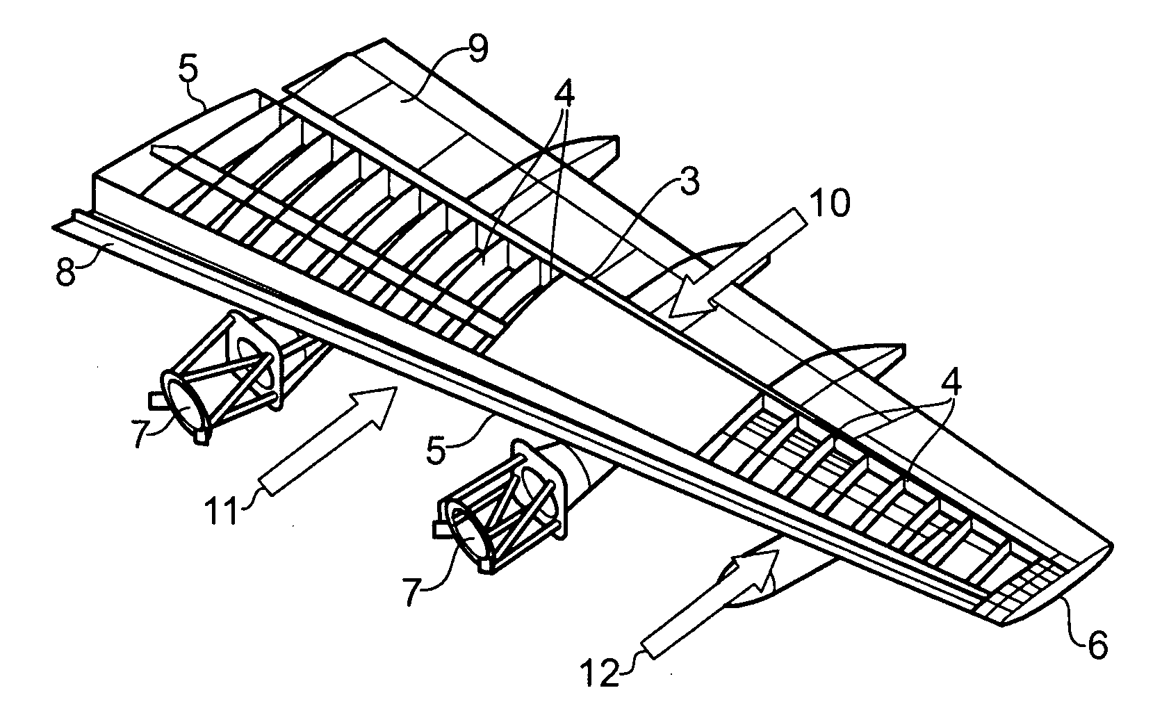
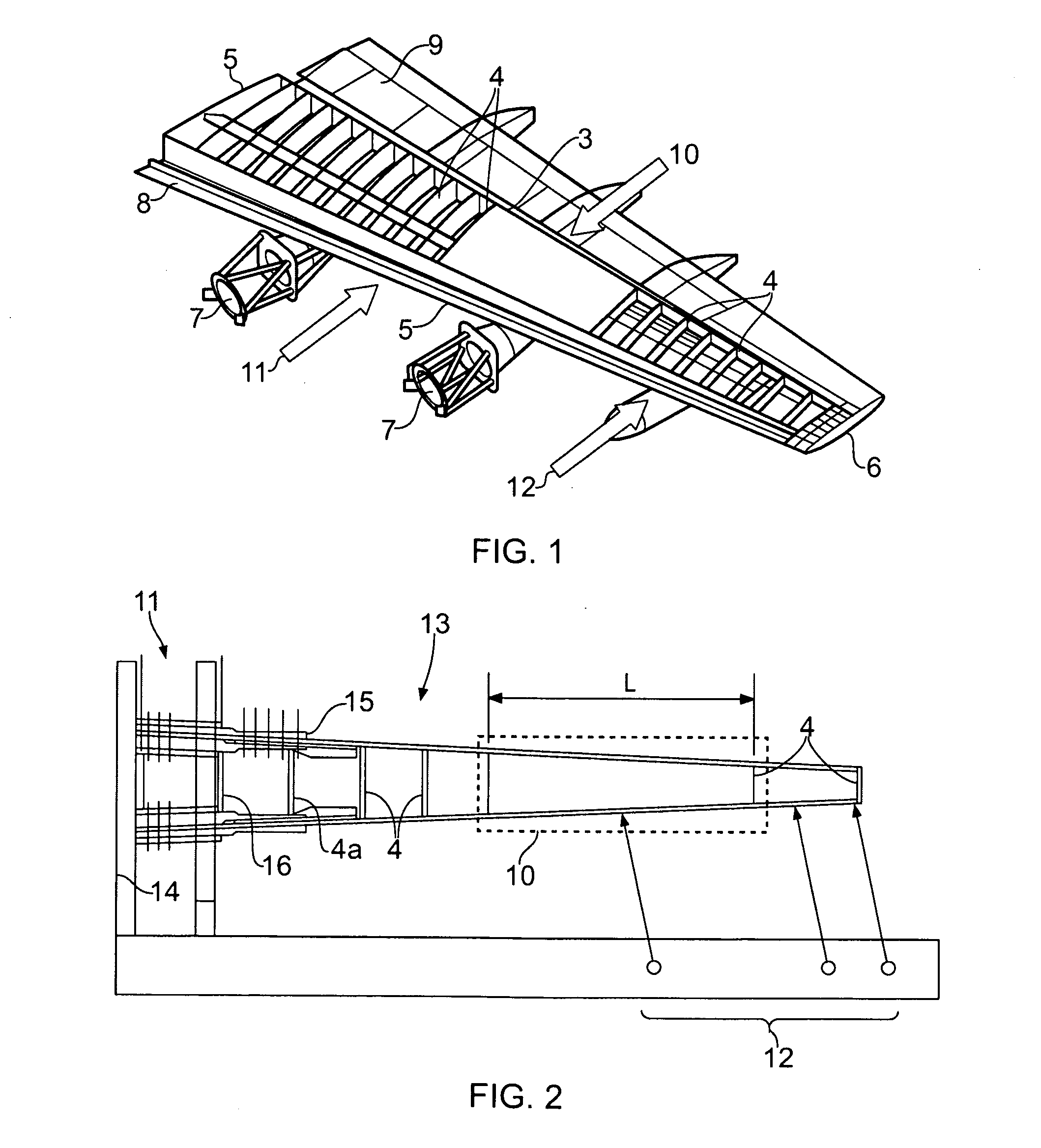
[0032]FIG. 1 illustrates an aircraft wing 1 for a medium / large transport jet aircraft, which includes a front spar 2, a rear spar 3, a plurality of chord-wise ribs 4, and upper and lower wing covers 5, 6 to form a typical wing box construction. Engine pylons 7 are slung beneath the wing. Leading edge structures 8 and trailing edge structures 9 are also shown in FIG. 1. The solid arrow indicates an area of interest 10 for conducting mechanical static and fatigue load tests combined with a thermal test on the wing 1.

[0033]Due to the size of the wing 1 it is not practicable to conduct the test on the entire wing, and so a test specimen comprising part of the wing box for the wing 1 will be used, which includes the area of interest 10. Arrow 11 indicates a grounding and diffusion area where the test specimen wing box will be mounted and loads in the wing box diffused into the mounting fixture. Arrow 12 indicates a load introduction area where loads will be introduced into the test spec...


PUM

PropertyMeasurementUnit
temperatureaaaaaaaaaa
constant temperatureaaaaaaaaaa

Abstract

Thermal test apparatus comprising a specimen supported by a fixture, a thermal shroud comprising a flexible insulating fabric forming an enclosure around at least a portion of the specimen, and a temperature controlled air supply connected to an opening formed in the enclosure for delivering a supply of temperature controlled air into the enclosure. Also, a method of conducting a thermal test.

Description

FIELD OF THE INVENTION[0001]The present invention relates to apparatus and method for conducting a thermal test on a specimen.BACKGROUND OF THE INVENTION[0002]As part of a test program for a structure, static and fatigue tests may need to be carried out on the structure at an elevated or lowered temperature. The test specimen may be heated / cooled and subjected to a variety of imposed mechanical load scenarios. This test program may be used, for example, to test the whole or part of an aircraft structure, or any other structure.[0003]In some circumstances, it is not practicable or necessary, to heat / cool the entire test specimen. For example, the size and geometry of the test rig supporting the specimen may hinder the use of some heating / cooling arrangements. Also, the thermal test may only be applicable to certain areas of the test specimen. For example, if the test specimen includes metallic and composite components then the thermal loading due to the thermal coefficients of the di...

Claims


Application Information

Patent Timeline
Patent Type & Authority Applications(United States)
IPC IPC(8): G01N3/00G01N25/00
CPCG01N25/72G01M99/002
Inventor DAVIES, PETER
Owner AIRBUS OPERATIONS LTD
Why Eureka
Try Eureka