SOFC-conduction

a fuel cell and conductor technology, applied in the direction of fuel cells, solid electrolyte fuel cells, electrical equipment, etc., can solve the problems of damage to enclosure walls, difficult control of conventional sofc systems, and inefficient thermal energy exchange between tail gas combustor and recuperator, etc., to achieve high thermal conductivity, manage thermal energy exchange, and reduce thermal gradients across the sofc system

Active Publication Date: 2019-10-15
UPSTART POWER INC
View PDF45 Cites 6 Cited by
  • Summary
  • Abstract
  • Description
  • Claims
  • Application Information

AI Technical Summary

Benefits of technology

[0017]It is a further object of the invention to provide interconnected thermal energy conduction pathways that extend across a plurality of different mechanical elements that are mechanically interfaced with each other in order to reduce thermal gradients across the SOFC system.
[0018]It is a still further object of the present invention to manage thermal energy exchange between different regions of a SOFC system hot zone by providing high thermal conductivity thermal mass elements in thermal communication with enclosure walls and with heat sources and heat exchangers to substantially stabilize the temperature of each region of the SOFC hot zone.4 BRIEF SUMMARY OF THE INVENTION
[0021]A tail gas combustor region is disposed inside the hot zone cavity for combusting a mixture of spent fuel and hot exhaust air exiting from the SOFC stack. Alternately the tail gas combustor region may be disposed outside the hot zone cavity e.g. surrounding the hot zone enclosure walls. The combustion region is at least partially bounded by the hot zone enclosure walls such that thermal energy received by the hot zone enclosure walls from combustion is then thermally conducted through the hot zone walls to other regions of the hot zone enclosure walls to reduce thermal gradients across the hot zone enclosure wall structure. The tail gas combustor region is lined by internal walls formed from a high temperature, corrosion resistant metal such as Hastelloy and or Inconel or ceramic coated steel. More general the liner material is a metal alloy having as its primarily component metal nickel. The liner or liners may be soldered in place in a manner that prevents gasses inside the tail gas combustor from oxidizing or otherwise damaging surfaces of the hot zone cavity and or surfaces of any thermal mass elements bounding the hot zone cavity.

Problems solved by technology

In short the thermal energy exchange both inside the tail gas combustor and inside the recuperator is not efficient.
The result is that conventional SOFC systems are notoriously difficult to control and often develop hot spots, e.g. in the combustion enclosures, that can damage the enclosure walls even burning through walls when a combustion enclosure wall gets too hot.
Alternately when the temperature of the SOFC system is lowered, e.g. by modulating a fuel input flow rate, incomplete fuel processing results in carbon formation on anode surfaces which ultimately leads to decreased electrical output and eventual failure.
However the temperature sensing and monitoring systems are costly and prone to failure due to the high operating temperatures of the SOFC systems (e.g. 350-1200° C.).
Moreover the need to modulate fuel input as a safety measure to avoid damaging the SOFC system leads to inefficient and variable electrical power output.
Other high temperature problems that have been addressed in conventional SOFC systems include the need to match or account for differences in the thermal coefficient of expansion of mating parts of dissimilar materials in order to avoid loosening between mating parts, cracking of ceramic elements or bending of metal elements, and the need to account for increased metal creep rates that occur at high temperature.
However chromium leached into incoming cathode air can poison the cathode material layer, so materials that contain chromium are not desirable along any of the incoming air conduits or heaters if cathode poisoning is to be avoided.
While some thermal energy is transferred between regions of conventional SOFC systems by thermal conduction, e.g. conducted across interconnected metal elements, the fact that hot and cold spots are still problematic in conventional SOFC systems suggests that thermal conduction is either too slow or insufficient to promote a uniform temperature across different regions of a conventional SOFC system.
This is due in part to the need to use specialty metals for the high temperature corrosive environment which have less than desirable thermal conductivity properties.

Method used


Image

  • SOFC-conduction
  • SOFC-conduction
  • SOFC-conduction

Examples


first embodiment

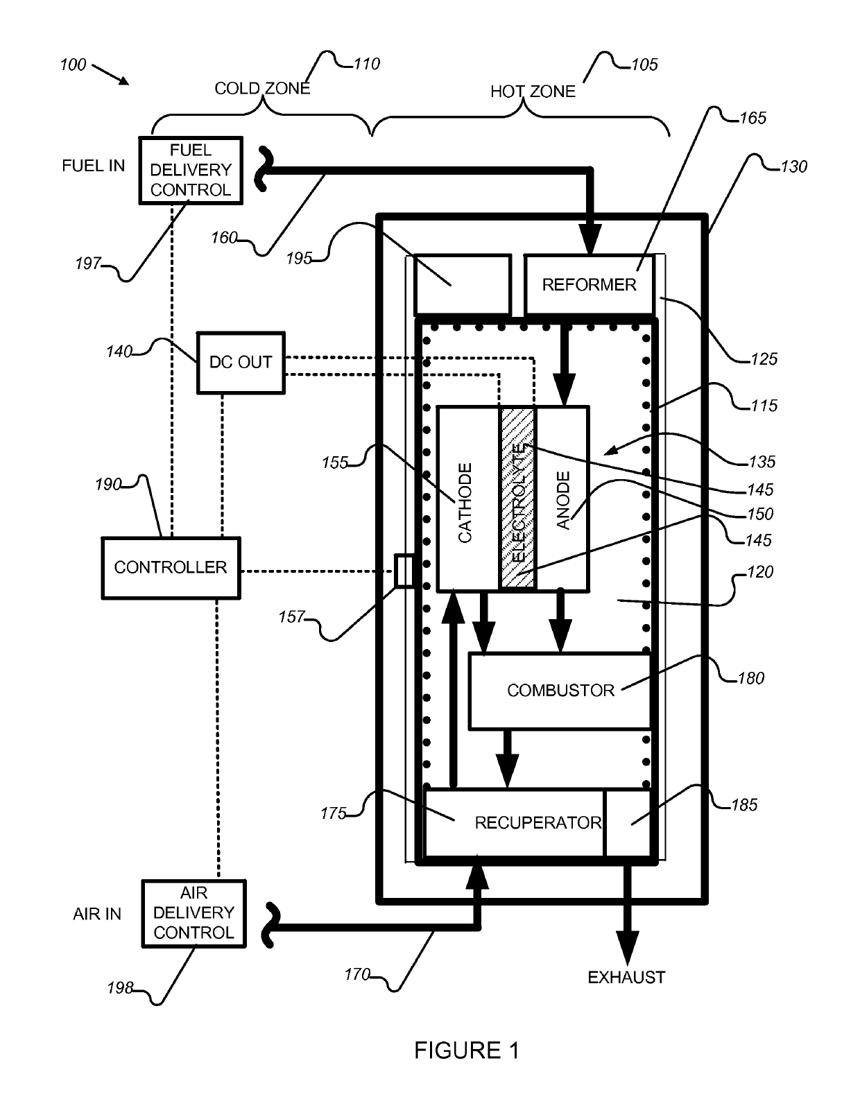
[0042]Referring to FIG. 1, a schematic diagram of the present invention depicts a Solid Oxide Fuel Cell (SOFC) system (100). The system (100) includes a hot zone (105), that includes at least one SOFC fuel cell and preferably a plurality of fuel cells forming a fuel cell stack maintained at a high operating temperature, and a cold zone (110) that includes fuel input and exhaust modules, a DC power output module and other control elements. Hot zone enclosure walls (115) are disposed to enclose a hot zone cavity (120) therein. A thermal insulation layer (130) surrounds the enclosure walls (115) to thermally insulate the hot zone (105). An air gap (125) is provided between the insulation layer (130) and a side wall of the hot zone enclosure walls (115) and the air gap provides a gas flow conduit for gases to flow from different regions of the hot zone to an exhaust port (185).

[0043]According to an important aspect of the present invention, the hot zone enclosure walls (115) and associa...

second embodiment

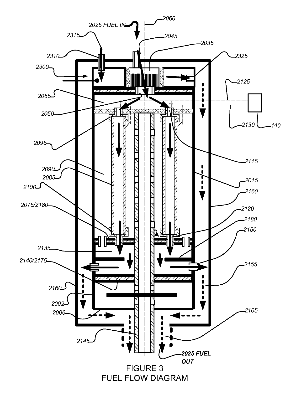
[0072]The fuel mixture (2025) is flowed over the anode material layer while the cathode gas, oxygen (air) is flowed over the cathode material layer in order to generate electrical current flow. The current flow passes out of the cell stack over the electrical terminals (2125) and (2130) to the DC terminals (140) and may be used to power external devices. It is noted that in other embodiments such as the second embodiment briefly described above, the anode and cathode surfaces can be reversed with the cathode layer on the inside diameter of the fuel cells and the anode layer on the outside diameter of the fuel cells and air flowing through the gas flow conduit formed by the fuel cells and fuel flowing over outside surface of the fuel cells without deviation from the present invention.

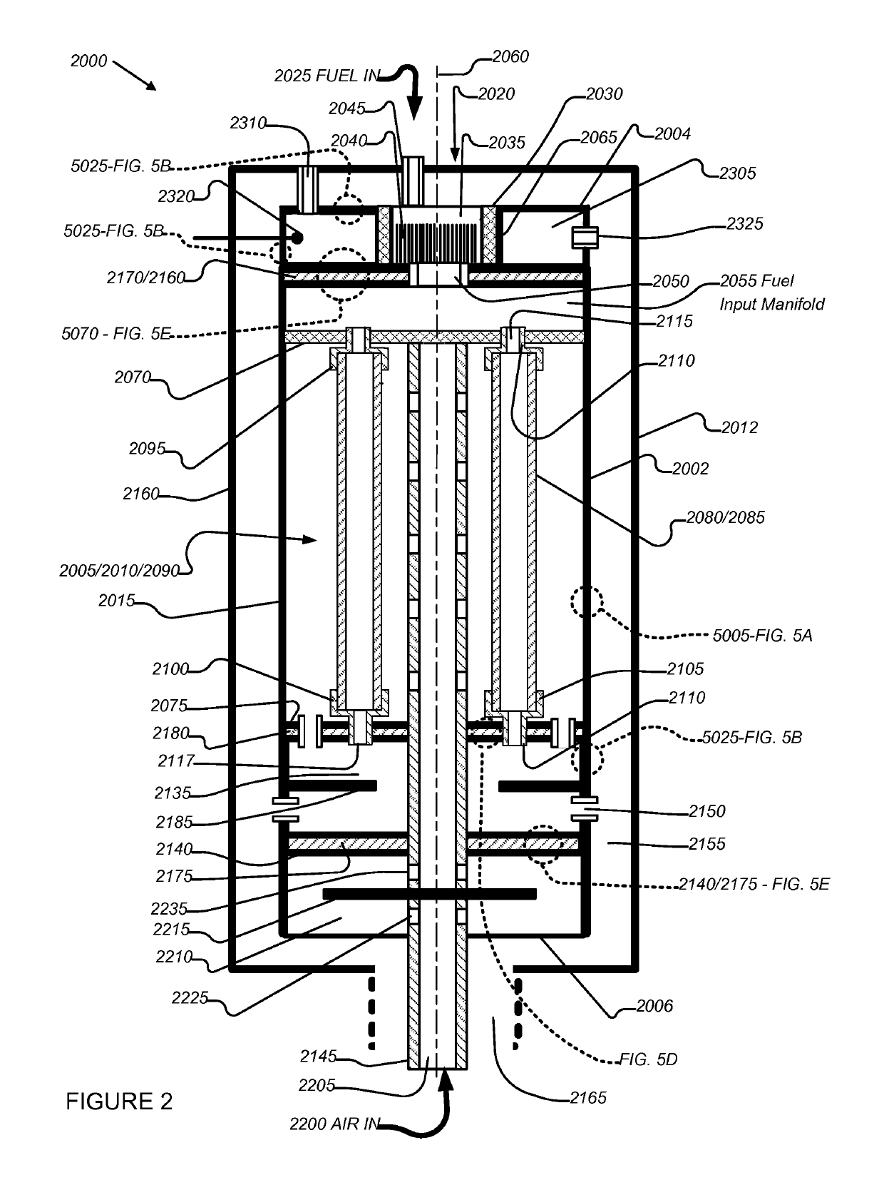
[0073]The fuel input manifold (2055) comprises a cylindrical chamber bounded by a disk-shaped top wall (2170) and the opposing disk shaped top tube support wall (2070). The disk-shaped top wall (2170) in...


PUM

PropertyMeasurementUnit
temperaturesaaaaaaaaaa
thicknessaaaaaaaaaa
thicknessaaaaaaaaaa

Abstract

A solid oxide fuel cell (SOFC) system included high thermal conductivity materials such as copper to increase thermal energy transfer by thermal conduction. The copper is protected from oxidation by nickel electroplating and protected from thermal damage by providing Hastelloy liners inside combustion chambers. Monel elements are used in the incoming air conduits to prevent cathode poisoning.

Description

CROSS-REFERENCE TO RELATED APPLICATIONS[0001]This application is a National Stage Entry of International Application No. PCT / US2014 / 059447 filed on Oct. 7, 2014, the contents of which are incorporated by reference as though fully set forth herein.1 COPYRIGHT NOTICE[0002]A portion of the disclosure of this patent document may contain material that is subject to copyright protection. The copyright owner has no objection to the facsimile reproduction by anyone of the patent document or the patent disclosure, as it appears in the Patent and Trademark Office patent files or records, but otherwise reserves all copyright rights whatsoever. The following notice shall apply to this document: © 2014 Protonex Technology Corporation.2 BACKGROUND OF THE INVENTION[0003]Field of the Invention[0004]The exemplary, illustrative, technology herein relates to Solid Oxide Fuel Cell (SOFC) systems, methods of use, and methods of manufacturing SOFC systems. In particular, the exemplary, illustrative techn...

Claims


Application Information

Patent Timeline
Patent Type & Authority Patents(United States)
IPC IPC(8): H01M8/04H01M8/12H01M8/04007H01M8/2475H01M8/2484H01M8/124
CPCH01M8/2475H01M8/2484H01M8/04067H01M2008/1293Y02E60/50H01M8/2425
Inventor PALUMBO, NATHANOSENAR, PAULPERSKY, JOSHUA
Owner UPSTART POWER INC
Why Eureka
Try Eureka