Cooling system for crystal used by laser

A cooling system and laser technology, applied in lasers, laser parts, phonon exciters, etc., can solve the problems of easy condensation and poor heat insulation of the device, increase thermal conductivity, reduce thermal lens effect, and ensure normal working effect

Inactive Publication Date: 2012-03-28
INST OF APPLIED ELECTRONICS CHINA ACAD OF ENG PHYSICS
View PDF5 Cites 7 Cited by
  • Summary
  • Abstract
  • Description
  • Claims
  • Application Information

AI Technical Summary

Problems solved by technology

[0003] In order to overcome the deficiencies of poor heat insulation and easy dew condensation in the cooling system of the prior art during the low-temperature cooling process of the Ti:Sapphire crystal, the present invention provides a cooling system for crystals used in lasers

Method used


Image

  • Cooling system for crystal used by laser
  • Cooling system for crystal used by laser
  • Cooling system for crystal used by laser

Examples


Embodiment 1

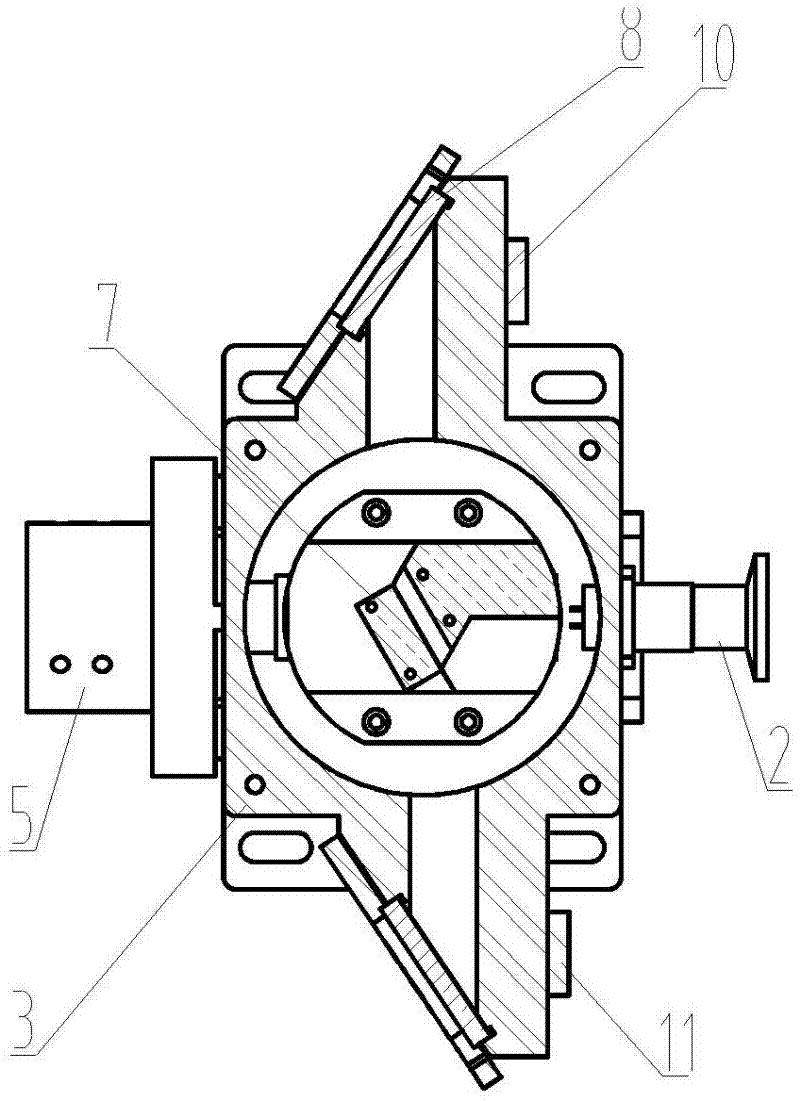
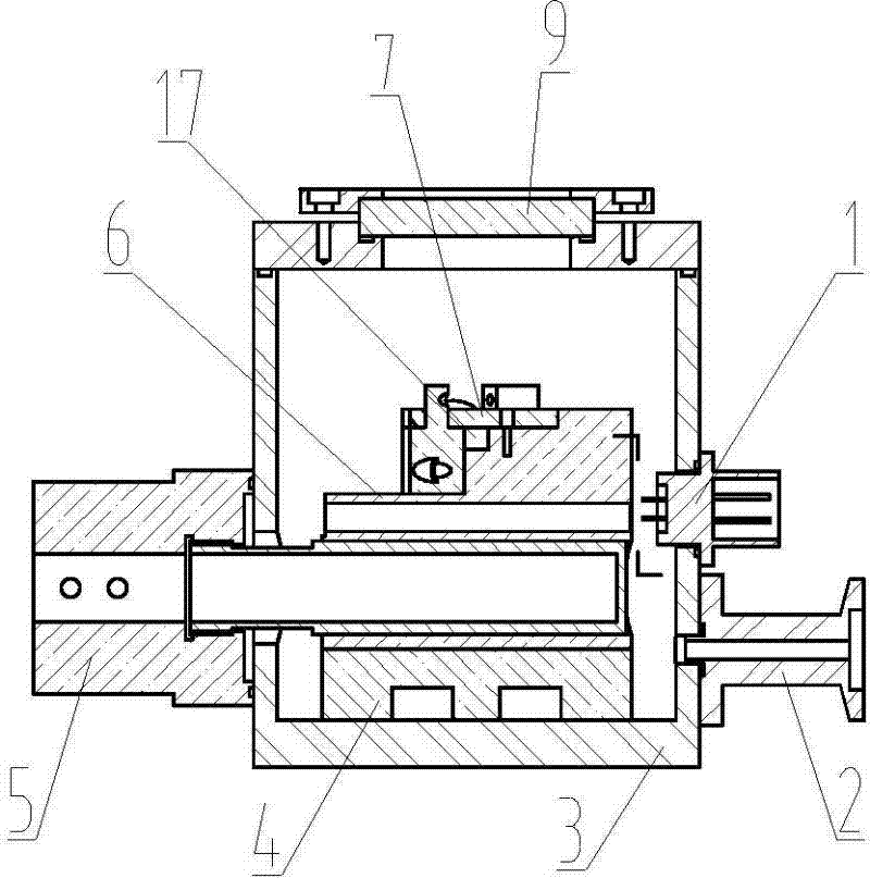
[0028] figure 1 It is a front view of a cooling system for a laser crystal of the present invention, figure 2 for figure 1 Sectional view on plane A-A in . exist figure 1 , figure 2 A cooling system for crystals used in lasers according to the present invention includes a crystal heat sink device, a temperature measuring device interface 1, a vacuum device interface 2, a vacuum chamber 3, a cooling interface device 5, a Brewster window 8, and an observation window 9; The crystal heat sink device includes a crystal heat sink 6, an inner and outer heat insulating pad 4, a crystal 17 and a crystal heat sink gland 7, wherein the crystal heat sink 6 is fixedly connected with the inner and outer heat insulating pad 4, and the crystal heat sink 6 is equipped with The crystal 17, the crystal heat sink gland 7 compresses the crystal 17 and is fixedly arranged on the crystal heat sink 6, and a through hole is arranged in the crystal heat sink 6; the vacuum chamber 3 is a cylindric...

Embodiment 2

[0040] In the present embodiment, the basic structure of the cooling system of a kind of laser crystal of the present invention is the same as that of Embodiment 1, the difference is,

[0041] In this embodiment, the inner and outer heat insulating pads 4 are made of heat insulating materials with a thermal conductivity of 0.08 W / (m·K).

[0042] The thickness of the inner and outer thermal insulation pads 4 is 15mm.

[0043] The heat conduction metal tube in the cooling device interface 5 has a thermal conductivity of 450W / (m·K), and the heat insulating seat is made of a heat insulating material with a thermal conductivity of 0.08W / (m·K).

[0044] The outer diameter of the heat-conducting metal tube in the cooling interface device 5 and the roughness of the through hole corresponding to the crystal heat sink 6 are both 0.8, and the gap is 0.01mm;

[0045] The unilateral gap between the outer diameter of the heat-conducting metal tube in the cooling interface device 5 and the ...


PUM


Abstract

The invention provides a cooling system for a crystal used by a laser. The cooling system is provided with a cooling interface device, a vacuum device interface, a temperature measuring device interface and installation interfaces of a brewster form, wherein the cooling interface device is externally connected with a cryogenic cooling system, the vacuum device interface is externally connected with a vacuum system and the temperature measuring device interface is externally connected with a temperature control feedback system. The external cryogenic cooling system that is connected with the cooling interface device provides a stable low-temperature environment for a crystal inside a vacuum chamber. The external vacuum system that is connected with the vacuum device interface provides a vacuum heat insulation environment for the crystal inside the vacuum chamber. The temperature control feedback system that is connected with the temperature measuring device interface carries out real-time feedback and regulation and control on the crystal temperature. And temperature control sheets that are installed near the installation interfaces of the brewster form are used for adjusting steam partial pressures around the brewster form to be below a condensation point. Therefore, according to the invention, thermal conductivity of the crystal used by a laser is increased; the thermal gradient is reduced; and a thermal lens effect is reduced; meanwhile, an occurrence of a condensation phenomenon can be avoided and normal work of the whole laser can be ensured.

Description

technical field [0001] The invention belongs to the field of crystal cooling for lasers, in particular to a cooling system for crystals for lasers. Used in the laser system for low-temperature adiabatic anti-condensation cooling of laser crystals (such as titanium sapphire). Background technique [0002] In the Ti:Sapphire laser pumped by the pump source, in order to fully tap the application potential of the Ti:Sapphire laser, it is necessary to solve key problems such as the thermal lens of the Ti:Sapphire crystal, which requires low-temperature cooling of the crystal to make the crystal heat The conductivity increases, the thermal gradient decreases, and the thermal lensing effect decreases. The selection of thermal insulation materials for the low-temperature cooling system of crystals currently used is unreasonable, and the thermal insulation structure adopts the structure of thin gaskets, resulting in poor thermal insulation performance; the observation window is bond...

Claims


Application Information

Patent Timeline
Patent Type & Authority Applications(China)
IPC IPC(8): H01S3/042
Inventor 石勇马毅唐淳王卫民庞毓崔玲玲周唐建张雷
Owner INST OF APPLIED ELECTRONICS CHINA ACAD OF ENG PHYSICS
Why Eureka
Try Eureka