High-frequency electro-optic position phase modulator

A phase modulator and electro-optic crystal technology, applied in the field of laser spectroscopy, can solve problems such as low Q value, lower crystal optical quality, and affect modulator efficiency, etc., achieve low half-wave voltage and improve microwave coupling efficiency

Active Publication Date: 2015-06-17
SHANGHAI INST OF OPTICS & FINE MECHANICS CHINESE ACAD OF SCI
View PDF3 Cites 0 Cited by
  • Summary
  • Abstract
  • Description
  • Claims
  • Application Information

AI Technical Summary

Problems solved by technology

This technology achieves quasi-velocity matching, and there is still a big gap compared with the efficiency of speed matching; the crystal polarity inversion technology requires the maximum thickness of the crystal, which limits the maximum aperture of the modulator. Generally, the aperture is smaller than At the same time, the polarity inversion technology will also reduce the optical quality of the crystal; the modulator uses a traveling wave electrode, and the Q value is low, usually in the tens of levels, which also affects the final efficiency of the modulator

Method used


Image

  • High-frequency electro-optic position phase modulator
  • High-frequency electro-optic position phase modulator
  • High-frequency electro-optic position phase modulator

Examples


Embodiment 1

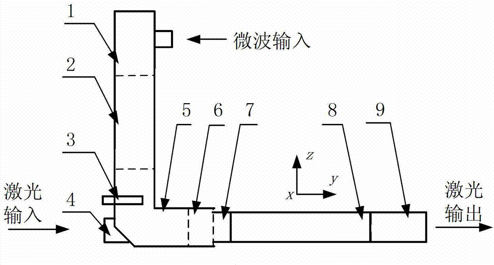
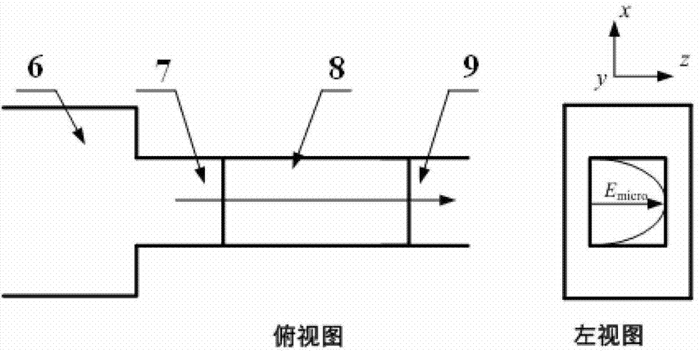
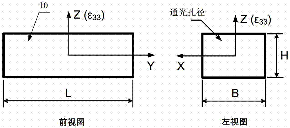
[0034] see first figure 1 , figure 1 It is a structural schematic diagram of the high-frequency electro-optic volume phase modulator of the present invention. It can be seen from the figure that the high-frequency electro-optic volume phase modulator of the present invention is composed of a waveguide coaxial converter 1, a first waveguide 2, an E-plane curved waveguide 5, a second waveguide 6, first cut-off waveguide 7, electro-optic crystal 8 and second cut-off waveguide 9, the first waveguide 2, the E-plane bend waveguide 5 and the second waveguide 6 are integrated, the other end of the first waveguide 2 Connected to the waveguide coaxial converter 1 through a standard flange, the first cut-off waveguide 7 and the second cut-off waveguide 9 are integrated with the light-transmitting surface package at both ends of the electro-optic crystal 8, and the The four sides of the electro-optic crystal 8 are gold-plated, and the electro-optic crystal 8 forms a high-frequency microw...

Embodiment 2

[0046] see first figure 1 , figure 1 It is a schematic structural diagram of an embodiment of the present invention. The difference between this embodiment and Embodiment 1 is that the waveguide described is a non-standard waveguide formed after the E-plane transition of the microwave band, such as Figure 4 As shown in the figure: GD_1-standard waveguide, GD_2-E-plane tapered transition waveguide, GD_3-non-standard waveguide.

[0047] The microwave operating frequency of the modulator, after the modulator is packaged, use a microwave network analyzer to test the TE of the modulator 10m Mode frequency, and as the actual microwave operating frequency of the modulator.

Embodiment 3

[0049] The difference between this embodiment and Embodiment 1 or Embodiment 2 is that the E-plane curved waveguide 5 is provided with an adjusting screw 3 to adjust the microwave coupling efficiency.

[0050] for example:

[0051] Take the bulk modulator with a microwave operating frequency of ~10GHz as an example, in the figure: 1 is the waveguide coaxial converter of the X-band; the first waveguide 2 is the E-plane tapered transition waveguide of the X-band; the screw 3 is M2; The hole 4 is 3×3mm; the curvature of the E-plane curved waveguide 5 is 90 degrees; the second waveguide 6 is a non-standard height waveguide; the first cut-off waveguide 7; the electro-optic crystal 8 is a four-sided gold-plated lithium niobate crystal; the second cut-off waveguide 9. The microwave operating frequency of the modulator is 10.3GHz, and the aperture of the modulator is 3×2mm, S 11 The parameter is less than -15dB. Narrowband pulsed laser with a wavelength of 1053nm and a pulse width ...


PUM


Abstract

The invention relates to a high-frequency electro-optic position phase modulator which structurally comprises a waveguide coaxial converter, a first waveguide, a bolt, a light through hole, an E-surface bent waveguide, a second waveguide, a first stopping waveguide, an electro-optic crystal and a second stopping waveguide. The high-frequency electro-optic position phase modulator can be used for restraining a stimulated brillouin effect of a laser system and uniformly and smoothly forming dispersion of a spectral angle of a high-power laser device; the high-frequency electro-optic position phase modulator has the characteristics that the microwave and optical wave phase velocities are matched, the modulating efficiency is high and the light caliber is large; and the high-frequency electro-optic position phase modulator is suitable for the microwave operating frequency range of 2-20GHz.

Description

technical field [0001] The invention relates to laser spectrum, especially a high-frequency electro-optical phase modulator used for suppressing the stimulated Brillouin effect (SBS) of a laser system and smoothing the angular dispersion of a high-power laser device. Background technique [0002] High-frequency electro-optic phase modulators generally use microwave signals to modulate the phase of light waves. This phase modulation can broaden the spectrum of narrow-band lasers: microwave signals are coupled into electro-optic crystals. Due to the transverse electro-optic effect of crystals, the sinusoidal electric field of microwave It is the high-frequency sinusoidal change of the crystal refractive index; if the s-polarized light wave passing through the crystal matches the phase velocity of the microwave, a high-frequency modulated phase quantity is introduced into the phase of the light wave. For the specific principle, please refer to: Literature Guo Fengzhen et al., " ...

Claims


Application Information

Patent Timeline
Patent Type & Authority Patents(China)
IPC IPC(8): G02F1/035
Inventor 姜有恩李学春周申蕾范薇林尊琪
Owner SHANGHAI INST OF OPTICS & FINE MECHANICS CHINESE ACAD OF SCI
Why Eureka
Try Eureka