Universally usable bar cutter head and use thereof

a cutter head and universal technology, applied in the field of universal useable bar cutter heads, can solve the problems of poor rigidity of the entire configuration made of cutter heads and cutters, high cost outlay, and inability to maintain high precision, etc., to achieve high precision, flexible use, and maintain high precision

Active Publication Date: 2010-05-06
KLINGELNBERG AG
View PDF11 Cites 11 Cited by
  • Summary
  • Abstract
  • Description
  • Claims
  • Application Information

AI Technical Summary

Benefits of technology

[0021]Several advantages of the invention are listed hereafter. The cutter head according to the invention is flexibly usable and nonetheless maintains the high precision of a conventional bar cutter head. The high precision is achieved in that there are high-precision recesses for receiving the bar cutters at the various cutter head nominal radii. Each recess can be applied precisely at the desired position using electro-erosion, for example. The recesses are each only as large as they must be in order to receive a bar cutter. Because only relatively small recesses are required, the rigidity of the cutter head remains essentially maintained. If longer, radially oriented recesses were provided, the rigidity would be significantly reduced.

Problems solved by technology

The precision of the position of the cutters, the stability of the cutter attachment, and the rigidity of the entire configuration made of cutter head and cutter is impaired by the use of such plates.
The cost outlay is especially high in particular if older cutter heads are to be replaced by new bar cutter heads, which may receive newer and more durable bar cutters, or are usable on newer bevel gear cutting machines.
The costs may be quite high if all old cutter heads must be replaced by corresponding new bar cutter heads.
These examples prove that the tool expenditure can be too large and costly for many users.

Method used


Image

  • Universally usable bar cutter head and use thereof
  • Universally usable bar cutter head and use thereof
  • Universally usable bar cutter head and use thereof

Examples


Embodiment Construction

[0036]Terms are used in connection with the present description, which are also used in relevant publications and patents. However, it is to be noted that the use of these terms is only to serve for better understanding. The ideas of the invention and the protective scope of the claims are not to be restricted in their extent by the specific selection of the terms. The invention may be transferred readily to other term systems and / or areas of specialization. The terms are to be applied appropriately in other areas of specialization.

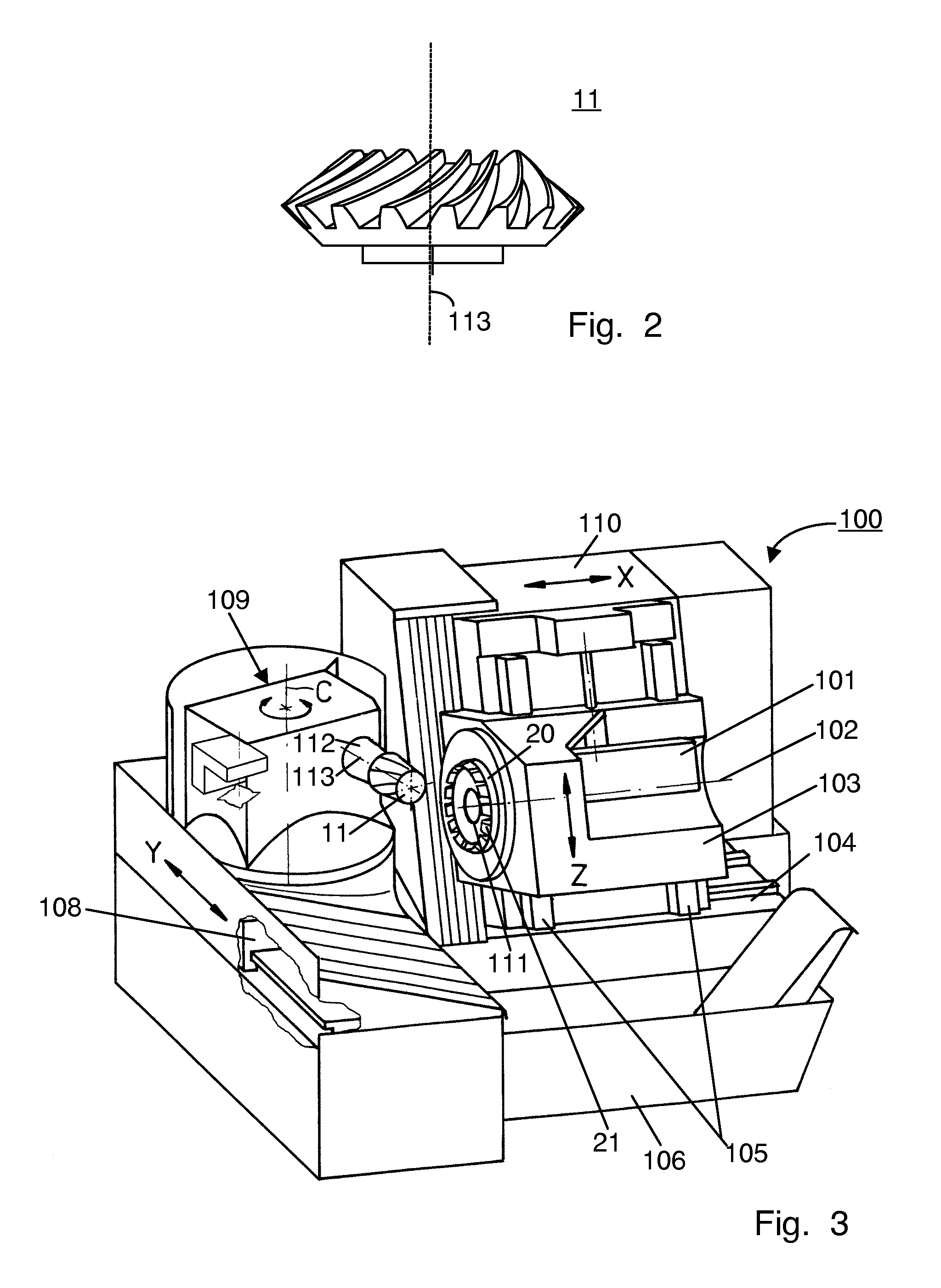
[0037]The schematic side view of a spiral-toothed bevel gear pinion 11 is shown in FIG. 2. This is a bevel gear pinion 11 having spiraling longitudinal flank lines. The invention may also be applied to the production of other bevel gear pinions 11 and crown wheels (e.g., hypoid bevel gears), which are producible in the single indexing method.

[0038]FIG. 3 shows a perspective illustration of the fundamental construction of a corresponding CNC machine 100 (a...


PUM

PropertyMeasurementUnit
mutual angleaaaaaaaaaa
angleaaaaaaaaaa
radius r2aaaaaaaaaa

Abstract

Bar cutter head (20) for receiving multiple bar cutters of a first bar cutter set, the bar cutter head (20) having n receptacle openings (25.1-25.6) for receiving n bar cutters of the first bar cutter set, which are all situated along a first concentric cutter head nominal circle having a first cutter head nominal radius (r1). A first spiral-toothed bevel gear (11) can be milled in the single-indexing method in this configuration. The bar cutter head (20) additionally has m receptacle openings (26.1-26.6) for receiving m bar cutters of a second bar cutter set, which are all situated along a second concentric cutter head nominal circle having a second cutter head nominal radius (r2). A second spiral-toothed bevel gear can be milled in the configuration having the m bar cutters. It is thus a universally-usable cutter head (20).

Description

CROSS REFERENCE TO RELATED APPLICATION[0001]This application claims the benefit of European Application No. 08 167 925.0, filed Oct. 30, 2008, the disclosure of which is herein incorporated by reference in its entirety.FIELD OF THE INVENTION[0002]The present invention relates to bar cutter heads for machining bevel gears, in particular spiral-toothed bevel gears in the single indexing method. The invention also relates to the use of such a universally usable cutter head for machining spiral-toothed bevel gears in the single indexing method.BACKGROUND OF THE INVENTIONPrior Art[0003]There are various types of bevel gears, these types being differentiated, inter alia, on the basis of the curve of the longitudinal flank lines. The following bevel gears are differentiated according to the curve of the longitudinal flank lines:straight-toothed bevel gearshelically-toothed bevel gearsspiral-toothed bevel gears.[0004]The term “spiral-toothed bevel gears” was presumably taken from the Americ...

Claims


Application Information

Patent Timeline
Patent Type & Authority Applications(United States)
IPC IPC(8): B23F9/10B23F21/22
CPCB23F9/10B23F9/105B23F21/223Y10T407/171Y10T407/1705Y10T409/108427Y10T409/104134Y10T409/104293Y10T409/103975Y10T407/17Y10T407/1725
Inventor DURR, ALEXANDER
Owner KLINGELNBERG AG
Why Eureka
Try Eureka