
Method of remotely adjusting a satiation and satiety-inducing implanted device
- Summary
- Abstract
- Description
- Claims
- Application Information
AI Technical Summary
Problems solved by technology
Method used
Image

Examples
first embodiment
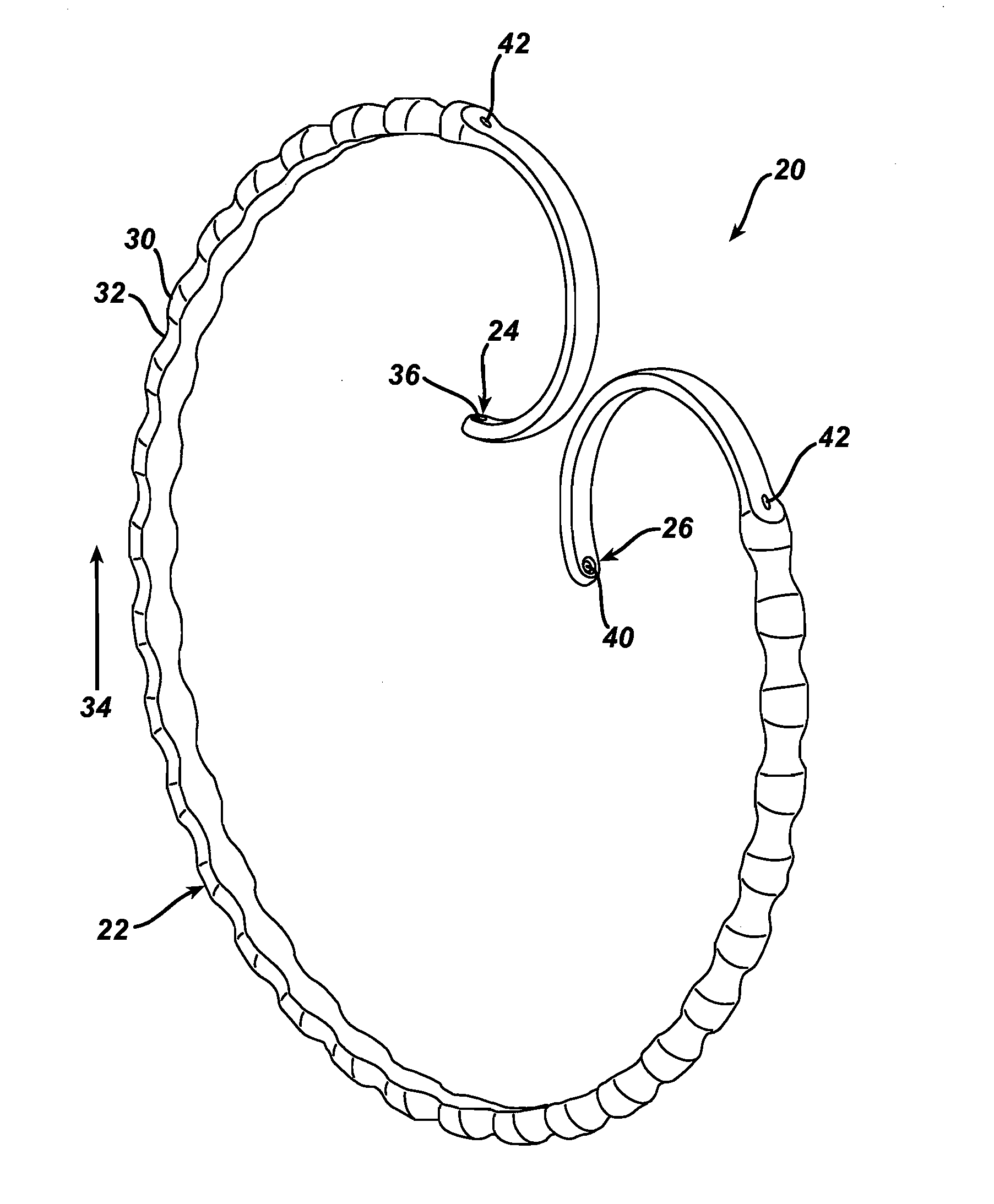
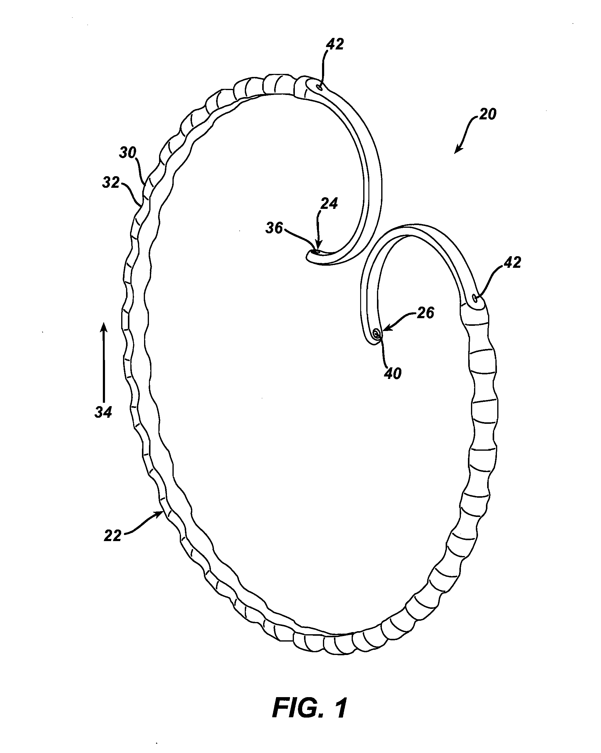
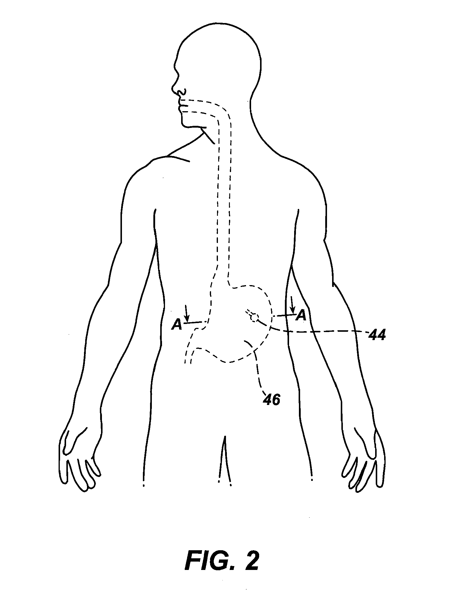
[0042]FIG. 3 shows a first embodiment for adjusting coil 20 through port 44. In this embodiment, an adjustment wire 52 is housed within a sheath 54. The adjustment wire and sheath extend through lumen 42 of coil 20. Wire 52 is securely attached at one opening of lumen 42 to one of the distal ends 24, 26 of coil 20. The other, free end of wire 52 extends through sheath 54 outside the opposite opening of lumen 42. To adjust coil 20, a knob 56 is disposed on the external side of port 44, as shown in FIG. 4. The free end of wire 52 extends through port 44 and is attached to knob 56. Wire 52 may be pulled externally through sheath 54 by turning knob 56 in a first direction. As knob 56 turns, pulling on wire 52, the wire tension is passed back into lumen 42 to the attached end of the wire. The tension on wire 52 shortens the length of the wire within lumen 42. When adjustment wire 52 is offset from the bending moment of coil 20 towards the inner diameter 110 of the coil, as shown in FIG. ...
second embodiment
[0044]FIG. 6 shows a second embodiment for percutaneously adjusting an implanted coil 20 through port 44. In this embodiment, a plurality of pieces of flexible material 60 extend through the open loop of coil 20. Flexible material 60 may, for example, be strands of suture material. Each of the suture strands 60 is attached at one end to hole 36 and at the opposite end to hole 40 to constrain coil 20 in a compressed configuration. Suture strands 60 have differing lengths to create different degrees of compression within coil 20. Initially, the shortest piece of suture is held tautly between the coil ends to compress the coil into a minimum size. To expand the size and shape of coil 20, a tool may be passed through port 44 to selectively sever one or more of the sutures 60. Alternatively, a tool may be passed trans-esophageally to cut sutures 60. The sutures are preferably severed in the order of increasing length, with the shortest suture cut first, to gradually expand the size of th...
third embodiment
[0046]FIG. 8 shows a third embodiment for percutaneously adjusting a coil 20 through port 44. In this embodiment, a winch 62 is embedded in one of the coil ends 24, 26. A first end of a suture material 64 is wound around winch 62, as shown in greater detail in FIG. 9A. A second end of the suture is securely attached to the other one of the coil ends 24, 26. Suture 64 is held between the coil end and winch 62 to maintain coil 20 in a compressed configuration. To expand the size of coil 20, winch 62 is turned in a first direction to increase the suture length between the winch and coil end. Alternatively, to reduce the size of coil 20, winch 62 is turned in a second direction to reduce the suture length and draw coil ends 24, 26 closer together. As shown in FIG. 9B, a torsional cable 66 extends from winch 62 through port 44 to operate the winch. Cable 66 is housed within a sheath 68 and attached at an external end to knob 56. When knob 56 is turned, cable 66 moves within sheath 68 to ...
PUM
 Abstract
Description
Claims
Application Information