

Gaming machine
a gaming machine and gaming technology, applied in the field of gaming machines, can solve problems such as heat generation in components, and achieve the effects of reducing the space for installing the gaming machine, preventing a malfunction of components, and reducing the space for gaming machines
- Summary
- Abstract
- Description
- Claims
- Application Information
AI Technical Summary
Benefits of technology
Problems solved by technology
Method used
Image

Examples
first embodiment
[0035]A gaming machine according to the first embodiment will be described in detail with reference to the drawings as embodied in a slot machine 1.
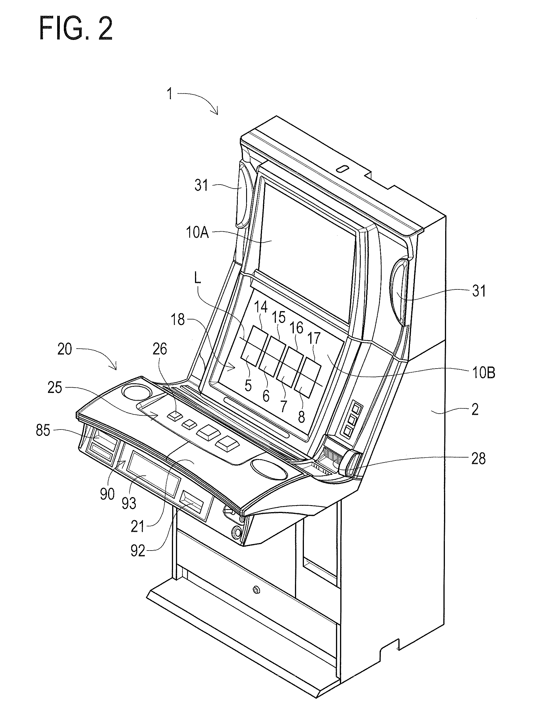
[0036]The features of the slot machine 1 according to the present invention will be described in detail with reference to the drawings. The slot machine 1 according to the first embodiment is a so-called hybrid-type slot machine. This hybrid-type slot machine has a known transmissive liquid crystal panel arranged in front of a plurality of mechanical reels. The plurality of mechanical reels are rotatably supported. This hybrid-type slot machine turns the transmissive liquid crystal panel into a transparent state when executing a game so as to allow the images of various symbols depicted on the outer peripheral surface of the mechanical reels to be displayed.
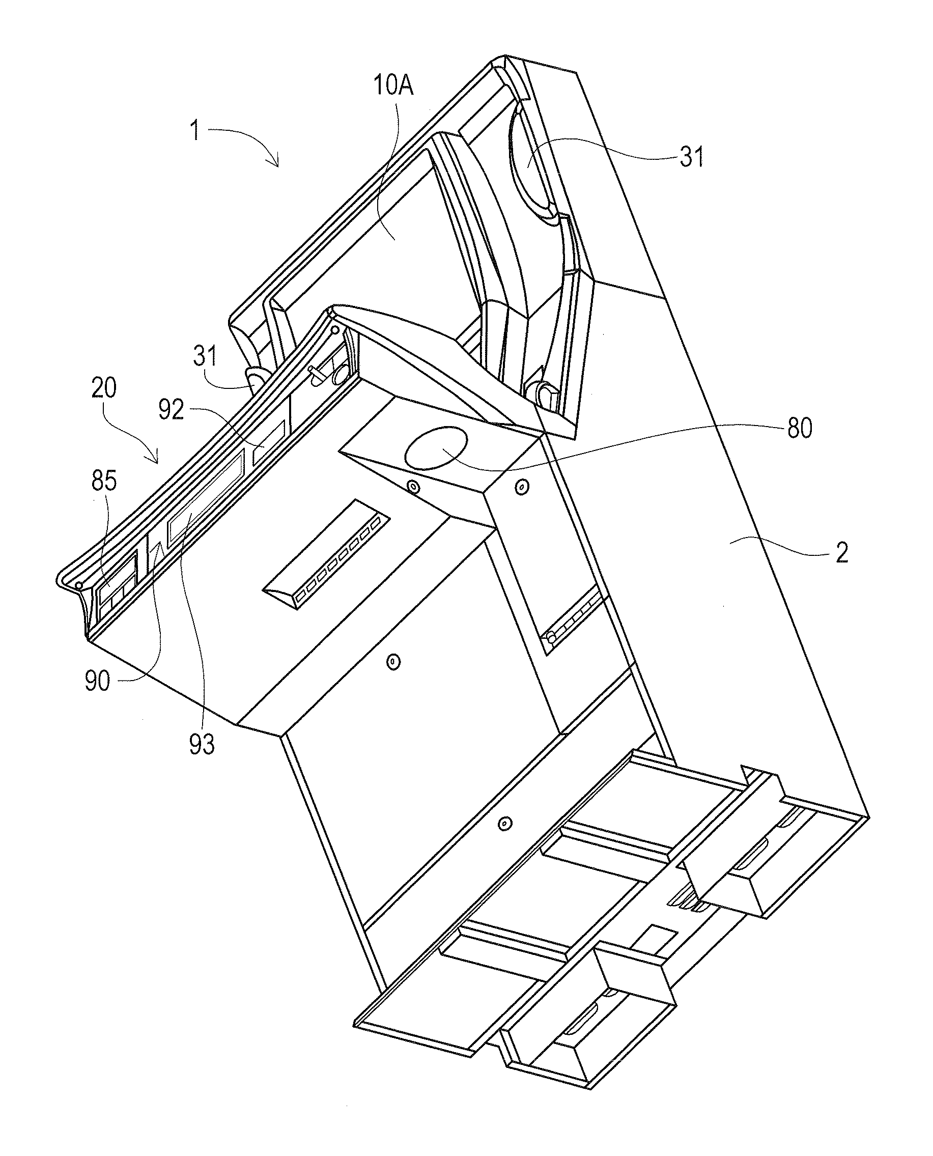
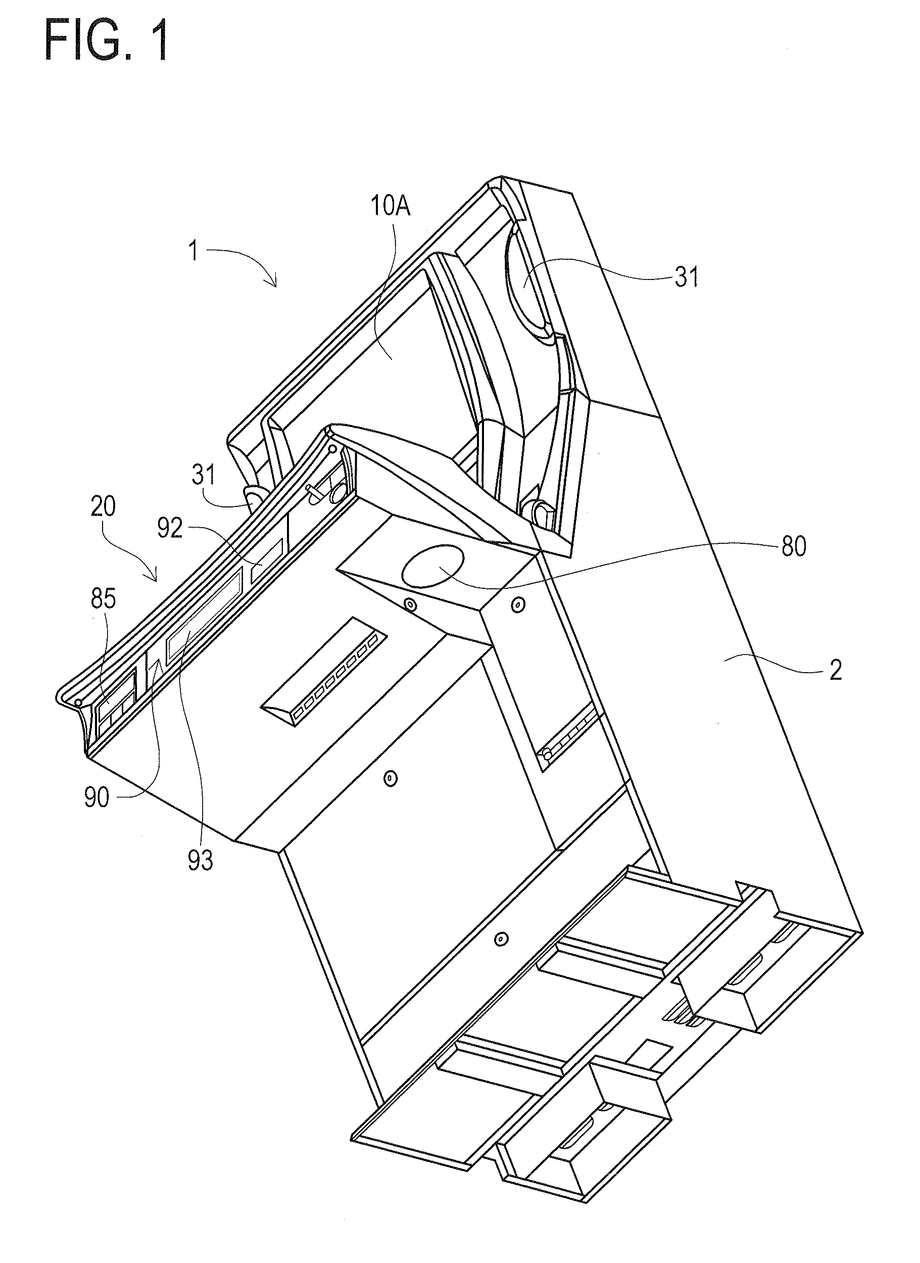
[0037]Also, the slot machine 1 is a slanted-type slot machine as is installed in game arcades such as casinos (refer to FIG. 1 and FIG. 2). In a case of the slanted-type slot machine,...
second embodiment
[0091]A gaming machine according to the second embodiment will be described in detail with reference to the drawings as embodied in a slot machine 101.
[0092]The features of the slot machine 101 according to the second embodiment will be described in detail with reference to the drawings. The slot machine 101 according to the second embodiment is a so-called hybrid-type slot machine. This hybrid-type slot machine has a known transmissive liquid crystal panel arranged in front of a plurality of mechanical reels. The plurality of mechanical reels are rotatably supported. This hybrid-type slot machine turns the transmissive liquid crystal panel into a transparent state when executing a game so as to allow the images of various symbols depicted on the outer peripheral surface of the mechanical reels to be displayed.
[0093]Also, the slot machine 101 is a slanted-type slot machine as is installed in game arcades such as casinos (refer to FIG. 6 and FIG. 7). In case of the slanted-type slot ...
PUM
 Abstract
Description
Claims
Application Information