Manipulator

Inactive Publication Date: 2010-06-10
AUTONETWORKS TECH LTD +2
View PDF5 Cites 19 Cited by
  • Summary
  • Abstract
  • Description
  • Claims
  • Application Information

AI Technical Summary

Benefits of technology

[0037]The fourth aspect of the present invention utilizes the first rotary control section formed in an approximate egg-like plate shape whose tip portion is referred to as indication portion and utilizes the second rotary control section formed in an approximate disk shape. Thus, a user can easily manipulate for the rotating operation, and can easily recognize a position indicated by the rotating first rotary control section. Therefore, it is possible to surely enhance the operability of the manipulator.
[0038]The fifth aspect of the present invention utilizes the first rotary control section having the indication portion which covers a part of the display. Thus, the indication portion can directly indicate the setup items shown on the display. Therefore, a user can recognize the setup item directly indicated by the indication portion of the first rotary control section as an object to be set. Hence, it is possible to enhance the operability of the manipulator and reduce user's wrong handling.
[0039]The sixth aspect of the present invention allows the first rotary control section to pivot in a direction intersecting to the rotating direction and allows the display to change the shown setup items based on the pivot movement. Thus, it is possible, by utilizing only the first rotary control section, to change the setup items shown by the display and to select one setup item from a plurality of shown setup items. Furthermore, it is possible to treat much more setup items for setting operations by utilizing the first rotary control section and the second rotary control section. Therefore, it is possible to increase the number of functions of the manipulator

Problems solved by technology

However, such a manipulator will cause a problem that there are an increasing number of menus shown on the display or an increasing complication of hierarchical structures of menus in response to an increasing number of devices and an increasing function of each

Method used


Image

  • Manipulator
  • Manipulator
  • Manipulator

Examples


Example

Embodiment 1

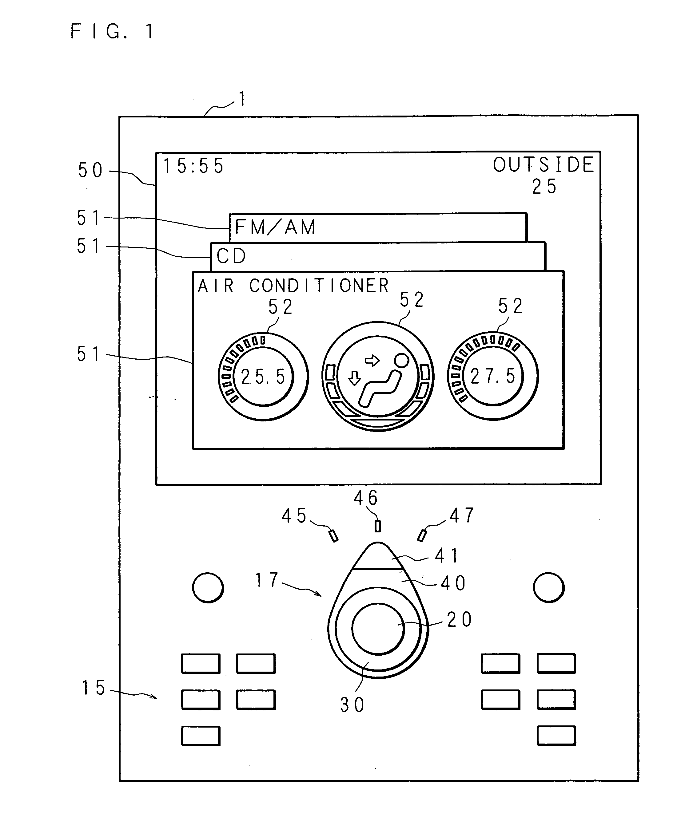
[0092]Hereinafter, the present invention is described in detail with reference to drawings illustrating an embodiment according to the present invention. FIG. 1 is a schematic view showing an appearance of a manipulator according to an embodiment 1 of the present invention. A manipulator 1 of the embodiment 1 is mounted on, for example, an instrument panel of a motor vehicle implying, for example, a car, and accepts various setting operations for devices mounted on the motor vehicle, such as an air conditioner, CD player and a radio tuner. The manipulator 1 includes: a display 50 that shows various information, setup items and the like; switch compound 17 that is composed of three switches; and a control panel 15 that is provided with different switches, buttons or the like.

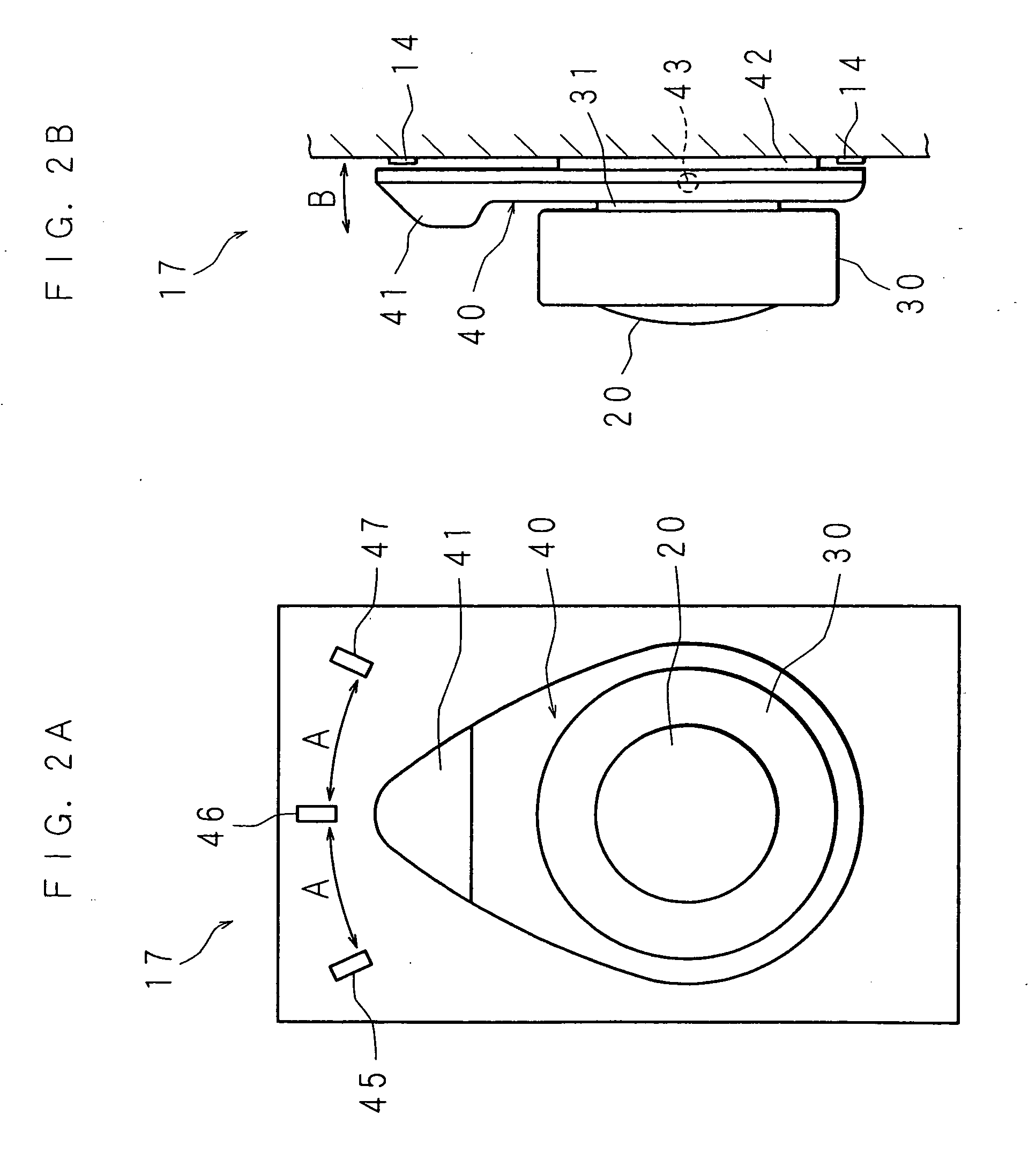
[0093]FIG. 2 is a schematic view showing a configuration of the switch compound 17 according to the embodiment 1 of the present invention. FIG. 2(a) shows the switch compound 17 in a plan view, and FI...

Example

Embodiment 2

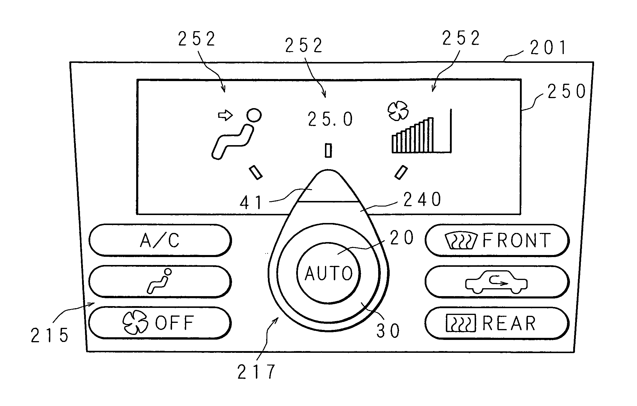
[0131]FIG. 7 is a schematic view showing an appearance of a manipulator 201 according to an embodiment 2 of the present invention. The manipulator 201 of the embodiment 2 includes a display 250, switch compound 217, control panel 215 having other switches and the like, and can accept settings of setup items 252 only for an air conditioner. The switch compound 217 of the manipulator 201 according to the embodiment 2 is configured similarly to the switch compound 17 of the manipulator 1 according to the embodiment 1, and is composed of a selection change switch 240, dial switch 30 and the push switch 20. However, the switch compound 217 according to the embodiment 2 has the selection change switch 240 failing to pivot, unlike the switch compound 17 according to the embodiment 1. In addition, the display 250 does not show a plurality of windows 51, unlike the display 50 according to the embodiment 1. The display 250 shows only three setup items 252 for the air conditioner.

[...

Example

Embodiment 3

[0137]As described above, the switch compound 17 of the manipulator 1 according to the embodiment 1 is configured to have the selection change switch 40 formed in an approximate egg-like shape and the dial switch 30 formed in an approximate disk shape that were arranged in a stacked manner. However, the switch compound according to the present invention is not limited to that configuration. FIG. 8 is a schematic view showing a configuration of a switch compound 317 according to an embodiment 3 of the present invention. FIG. 8(a) illustrates a plan view of the switch compound 317 and FIG. 8(b) illustrates a cross section view of the switch compound 317.

[0138]The switch compound 317 according to the embodiment 3 has a selection change switch 340 formed in an approximate egg-like shape in a plan view, dial switch 330 formed in an approximate round shape in a plan view and a push-button switch 320 formed in an approximate round shape in a plan view. The selection change swit...


PUM


Abstract

A selecting operation and a setting operation for setup items shown on a display are performed with using a selection change switch that can in steps rotate to three positions indicated by marks and a dial switch that is stacked on the selection change switch. The display shows three setup items at three locations. In a case that the selection change switch is rotated and a tip portion of the selection change switch indicates a position, it is thought that the selection operation is performed to select a setup item shown at a location corresponding to the indicated position. Then, the setting operation for the selected setup item is performed by rotating the dial switch. When the selection change switch has pivoted toward near side or far side, a window to be shown at the foreground is changed on the display.

Description

BACKGROUND OF THE INVENTION[0001]1. Field of the Invention[0002]The present invention relates to a manipulator that accepts setup operations to manipulate electric devices, such as a volume setting of an audio device and a temperature setting of an air conditioner.[0003]2. Description of Related Art[0004]Conventionally, it is known to mount different electric devices on a motor vehicle, such as a car navigation device, audio device and an air conditioner (AC), in order to improve comfort for a driver and a passenger riding on the motor vehicle. A manipulator is arranged near a driver seat, for example, on an instrument panel of the motor vehicle, which includes a plurality of switches, buttons and the like for manipulating these devices. Recently, there are an increasing number of devices mounted on a motor vehicle and an increasing number of functions added to each device. Thus, this tendency requires more switches, buttons and the like to manipulate these devices, and causes probl...

Claims


Application Information

Patent Timeline
IPC IPC(8): G06F3/033G06F3/048G06F3/0362
CPCB60H1/00985G06F3/0338G06F3/0362H01H25/00H01H9/165H01H19/14H01H21/22G06F3/048
Inventor YONEJI, OSAMU
Owner AUTONETWORKS TECH LTD
Why Eureka
Try Eureka