Control system of industrial machine

Active Publication Date: 2020-01-23
FANUC LTD
View PDF0 Cites 0 Cited by
  • Summary
  • Abstract
  • Description
  • Claims
  • Application Information

AI Technical Summary

Benefits of technology

The present invention aims to provide a control system for industrial machines that can efficiently and effectively match and equalize the content information of various data between devices, reducing processing time and burden during operation. The invention uses identifiers to distinguish data regions that were changed and transfer the changed data region between devices, allowing for efficient content information matching. This significantly reduces processing time for data updating and extraction, enhancing operability.

Problems solved by technology

However, the regions of each type of data are, for example, divided further into a plurality of regions, and in such a case, it is impossible to find out (rapidly find out) in which type region, or further, which divided region, or even further, which part of the enormous amount of data a change was made.

Method used


Image

  • Control system of industrial machine
  • Control system of industrial machine
  • Control system of industrial machine

Examples


first embodiment

[0032]A control system of an industrial machine according to the present invention will be described hereinafter with reference to FIGS. 1 to 5.

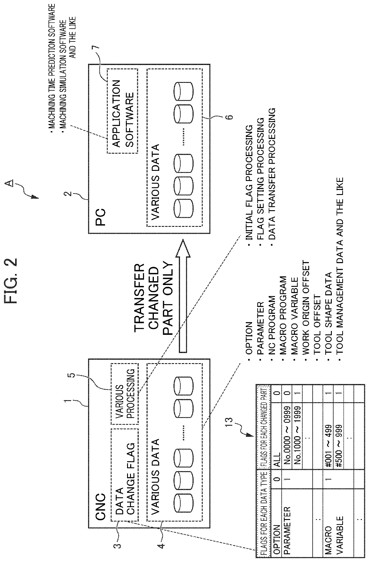
[0033]Here, for the present embodiment, description will be given using a case where changed data is transferred between one CNC on the machine tool side and one PC, that is, between one device and another device so as to be matched and equalized, as an example. It should be noted that, although the industrial machine according to the present invention is assumed to be a machine tool (the present device being the machine tool and the other device being the PC) in the description of the present embodiment, needless to say, the present invention can be applied to other industrial machines as well.

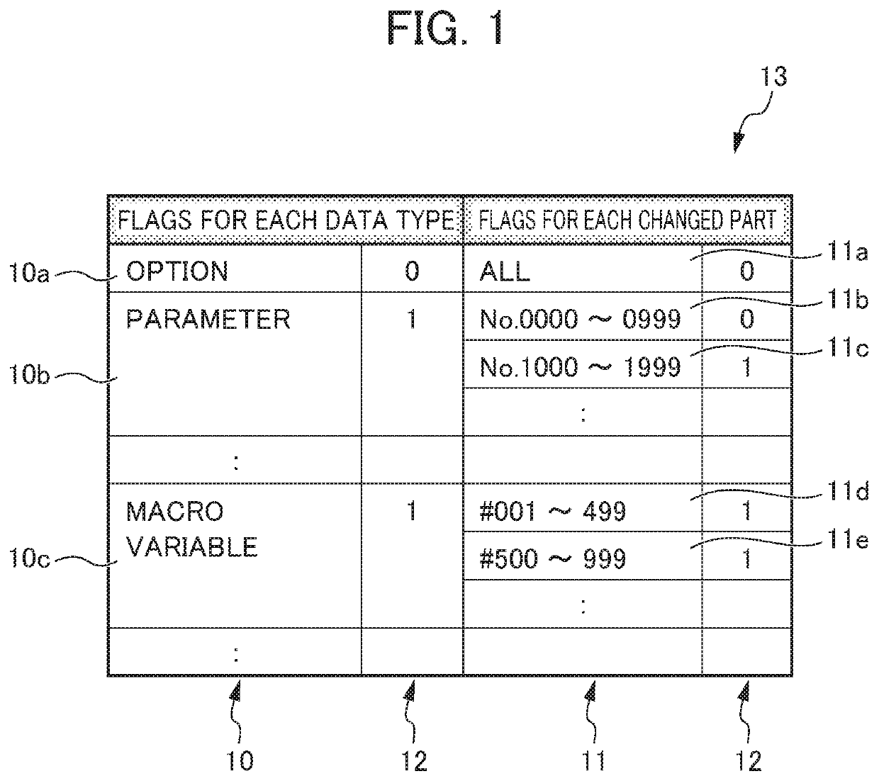
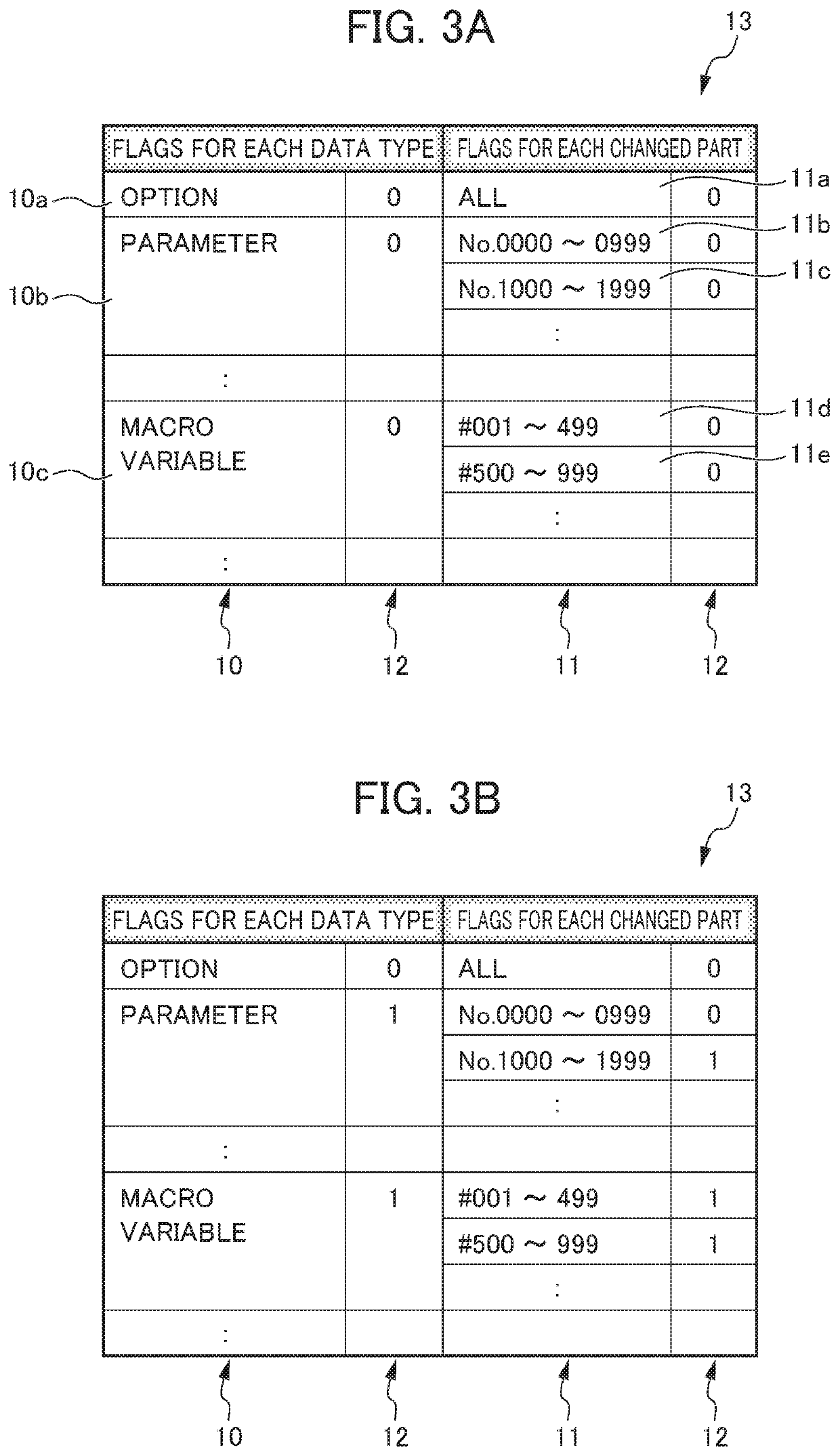
[0034]A control system A of an industrial machine according to the present embodiment is a control system and method of a “flag system” type which, as shown in FIGS. 1 and 2, uses a “changed data identification list”13 within a CNC 1, the list 13 comp...

second embodiment

[0054]Hereinafter, a control system of an industrial machine according to the present invention will be described with reference to FIGS. 6 to 10.

[0055]Here, in the present embodiment, a description will be given using a case where changed data is transferred between one CNC and two PCs, that is, between one device and two (plural) devices, so as to be matched and equalized, as an example. It should be noted that, although the industrial machine according to the present invention is assumed to be a machine tool (the present device being the machine tool and the other devices being the PCs) in the description of the present embodiment, needless to say, the present invention can be applied to other industrial machines as well. In the present embodiment, configurations which are the same as those of the first embodiment are identified with the same reference numerals, and the detailed description thereof will be omitted.

[0056]A control system B of an industrial machine according to the...


PUM


Abstract

An object of the present invention is to provide a control system of an industrial machine that can efficiently and effectively match and equalize the content information of various data between devices of the industrial machine. The invention is a control system of an industrial machine for matching data in the present device with data in one or more other devices, wherein the control system comprises a changed data identification list including: the regions of a type data storage unit serving as the superordinate class of type data; the regions of a subdivision data type storage unit serving as a subordinate class; and an identifier storage unit indicating identifiers which, when data in each of the regions is changed, identify the change of the data, the present device comprises: a changed data identification list storage unit storing the changed data identification list; a present-device-side data storage unit storing various data; and an updated data processing unit, and the other device comprises: an other-device-side data storage unit storing various data; and an operation execution unit using the various data to perform a desired operation.

Description

[0001]This application is based on and claims the benefit of priority from Japanese Patent Application No. 2018-136745, filed on 20 Jul. 2018, the content of which is incorporated herein by reference.BACKGROUND OF THE INVENTIONField of the Invention[0002]The present invention relates to a control system and a control method of an industrial machine such as a machine tool, a robot, a PLC, a transport machine, a measuring device, a testing device, a press machine, a press-fitting device, a printing machine, a die casting machine, an injection-molding machine, a food machine, a packaging machine, a welding machine, a washing machine, a coating machine, an assembly device, a mounter, a woodworking machine, a sealing device or a cutting machine, and more particularly, relates to a control system and a method for matching changed data between devices, such as between a CNC on a machine tool side and a PC or between a plurality of CNCs.Related Art[0003]As is already known, in the field of ...

Claims


Application Information

Patent Timeline
IPC IPC(8): G05B19/408
CPCG05B2219/33252G05B19/4083G05B2219/35356
Inventor MORISAKI, KAZUHIKO
Owner FANUC LTD
Why Eureka
Try Eureka