Generating a mission plan for capturing aerial images with an unmanned aerial vehicle

a technology of aerial images and mission plans, applied in the field of digital mission plans for unmanned aerial vehicles, can solve the problems of not being able to account for prohibited flight areas, unable to achieve the effect of capturing aerial images, and being unable to fly in certain areas

Active Publication Date: 2016-11-29
SKYCATCH
View PDF22 Cites 97 Cited by
  • Summary
  • Abstract
  • Description
  • Claims
  • Application Information

AI Technical Summary

Benefits of technology

[0011]Embodiments of the present disclosure provide benefits and/or solve one or more of the foregoing or other problems in the art with systems and methods for generating UAV mission plans. For example, in one or more embodiments, systems and methods solidify less volatile portions of a flight missi...

Problems solved by technology

Some conventional automated flight systems have been developed to address this client demand, but these conventional systems have various problems and limitations.
For example, some conventional automated flight systems can capture digital aerial images of a target site, but fail to account for prohibited flight areas.
For instance, many industrial and commercial clients seek to capture digital aerial images of a site but are prohibited from flying in certain areas as a result of no-flight zones, uncooperative adjacent property owners, sensitive areas, or physical obstacles (e.g., powerlines, buildings, etc.).
Common automated UAV flight systems typically fail to generate flight plans that accommodate prohibited flight areas.
Similarly, many conventional automated UAV flight systems fail to accommodate irregular, arbitrary flight areas.
For instance, some common automated flight systems can generate a flight plan that flies over a rectangular target area, but cannot generate a flight plan that stays within more complex, arbitrary polygons.
Known automated flight s...

Method used


Image

  • Generating a mission plan for capturing aerial images with an unmanned aerial vehicle
  • Generating a mission plan for capturing aerial images with an unmanned aerial vehicle
  • Generating a mission plan for capturing aerial images with an unmanned aerial vehicle

Examples


Embodiment Construction

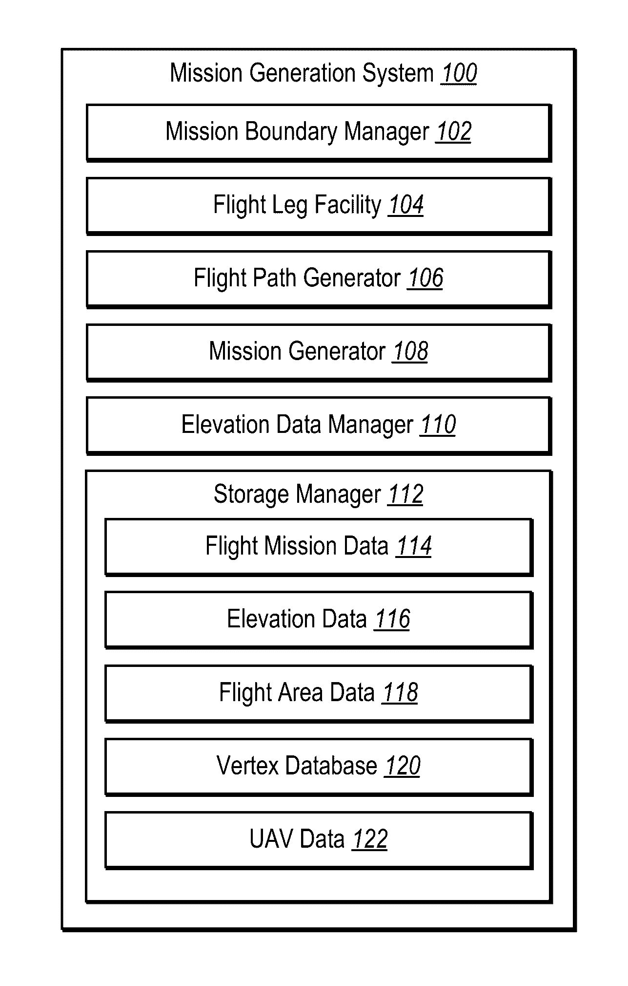
[0038]The present disclosure includes various embodiments and features of a mission generation system and corresponding processes that produce mission plans for capturing aerial images of a target site by a UAV. In particular, in one or more embodiments the mission generation system generates flight legs for traversing a target site and identifies optimal or near-optimal connections between the flight legs utilizing one or more linking algorithms. The mission generation system can generate a flight path that remains within a mission boundary. Moreover, the mission generation system can incorporate the flight path into a mission plan for capturing aerial images of a target site utilizing a UAV.

[0039]For example, in one or more embodiments the mission generation system identifies a mission boundary defining a UAV flight area. Specifically, the mission generation system identifies a mission boundary that encompasses a target site for capturing a plurality of aerial images by a UAV. The...


PUM


Abstract

Systems and methods are disclosed for generating a digital flight path within complex mission boundaries. In particular, in one or more embodiments, systems and methods generate flight legs that traverse a target site within mission boundaries. Moreover, one or more embodiments include systems and methods that utilize linking algorithms to connect the generated flight legs into a flight path. Moreover, one or more embodiments include systems and methods that generate a mission plan based on the flight path. In one or more embodiments, the generated mission plan enables a UAV to traverse a flight area within mission boundaries and capture aerial images with regard to the target site.

Description

BACKGROUND[0001]1. Technical Field[0002]One or more embodiments of the present disclosure relate generally to digital mission plans for unmanned aerial vehicles (UAVs). More specifically, one or more embodiments of the present disclosure relate to systems and methods for generating a digital mission plan for capturing aerial images within a mission boundary utilizing a UAV.[0003]2. Background and Relevant Art[0004]Individuals and businesses increasingly utilize digital aerial images to capture information regarding target sites. Indeed, in light of advances in unmanned aerial vehicles (UAVs), digital aerial photography has become increasingly affordable, and therefore accessible, for individual, industrial, and commercial applications. For instance, individuals now commonly utilize UAVs to capture digital aerial images of homes, places of interest, or even recreational activities.[0005]In many applications, individuals and businesses seek to capture digital aerial images utilizing d...

Claims


Application Information

Patent Timeline
IPC IPC(8): G08G5/00G01C21/34G05D1/00B64C39/02
CPCG08G5/0034G05D1/0094G01C21/3446B64C39/024B64C2201/123B64C2201/127B64C2201/141G05D1/0202G08G5/006G08G5/0069G08G5/0086B64U2101/30B64U10/14
Inventor TENG, YIFEICHEN, DAVIDSTUART, PATRICK
Owner SKYCATCH
Why Eureka
Try Eureka