Generating a mission plan for capturing aerial images with an unmanned aerial vehicle

a technology for aerial images and mission plans, applied in vehicle position/course/altitude control, process and machine control, instruments, etc., can solve problems such as failure to account for prohibited flight areas, and difficulty in achieving the effect of capturing aerial images

Active Publication Date: 2017-04-20
SKYCATCH
View PDF1 Cites 40 Cited by
  • Summary
  • Abstract
  • Description
  • Claims
  • Application Information

AI Technical Summary

Benefits of technology

[0014]By generating a flight path within the missionary boundary utilizing the flight legs, in one or more embodiments, the disclosed systems and methods can avoid prohibited areas. Thus, for example, a system can define a mission boundary that corresponds to a no-flight zone and generate a flight plan that remains within the mission boundary. Moreover, by building a flight plan utilizing the flight vertices and the flight legs, one or more embodiments of the disclosed systems and methods can accommodate irregular, arbitrary mission boundaries. For instance, one or more embodiments of the disclosed systems and methods can generate a flight path that stays within convex polygons, concave polygons, polygons with a variety of corners, or polygons with sides of varying lengths and angles.
[0016]Furthermore, by identifying flight legs and then building a flight path from the identified flight legs utilizing one or more linking algorithms, the disclosed systems and methods can generate flight missions quickly (i.e., with reduced processing time). Moreover, the disclosed systems and methods provide a user interface that allows users to flexibly and intuitively generate flight missions with regard to a variety of target sites and site conditions.

Problems solved by technology

Some conventional automated flight systems have been developed to address this client demand, but these conventional systems have various problems and limitations.
For example, some conventional automated flight systems can capture digital aerial images of a target site, but fail to account for prohibited flight areas.
For instance, many industrial and commercial clients seek to capture digital aerial images of a site but are prohibited from flying in certain areas as a result of no-flight zones, uncooperative adjacent property owners, sensitive areas, or physical obstacles (e.g., powerlines, buildings, etc.).
Common automated UAV flight systems typically fail to generate flight plans that accommodate prohibited flight areas.
Similarly, many conventional automated UAV flight systems fail to accommodate irregular, arbitrary flight areas.
For instance, some common automated flight systems can generate a flight plan that flies over a rectangular target area, but cannot generate a flight plan that stays within more complex, arbitrary polygons.
Known automated flight systems cannot accommodate such irregular target sites or generate flight plans that will stay within irregular flight areas.
These systems, however, fail to adequately plan for changes in elevation with regard to the ground surface or obstacles.
Thus, for example, common automated UAV flight systems cannot generate a mission plan with altitude data (i.e., changing z coordinates) that properly accounts for elevation data with regard to the target site.
Finally, many common automated flight systems are time consuming and difficult to use, as well as rigid, providing a user with very few options in how a UAV will traverse a target site.
Common systems struggle to satisfy user desire for fast, simple, and flexible operation, particularly in light of the fact that a near-infinite number of possibilities exist with regard to traversing any given target site to capture digital aerial images utilizing a UAV.
Accordingly, a number of problems and disadvantages exist with conventional systems for creating a mission plan for a UAV to capture digital aerial images of a target site.

Method used


Image

  • Generating a mission plan for capturing aerial images with an unmanned aerial vehicle
  • Generating a mission plan for capturing aerial images with an unmanned aerial vehicle
  • Generating a mission plan for capturing aerial images with an unmanned aerial vehicle

Examples


Embodiment Construction

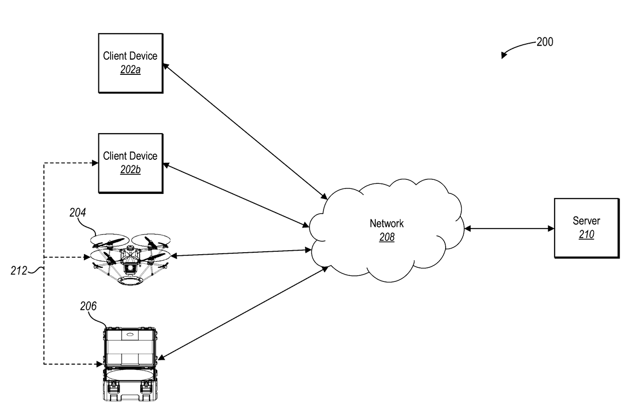
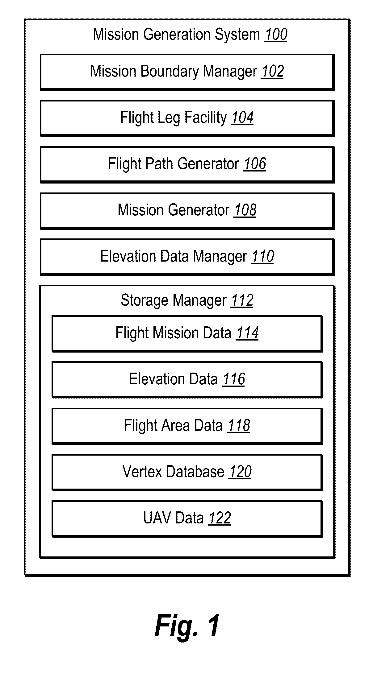
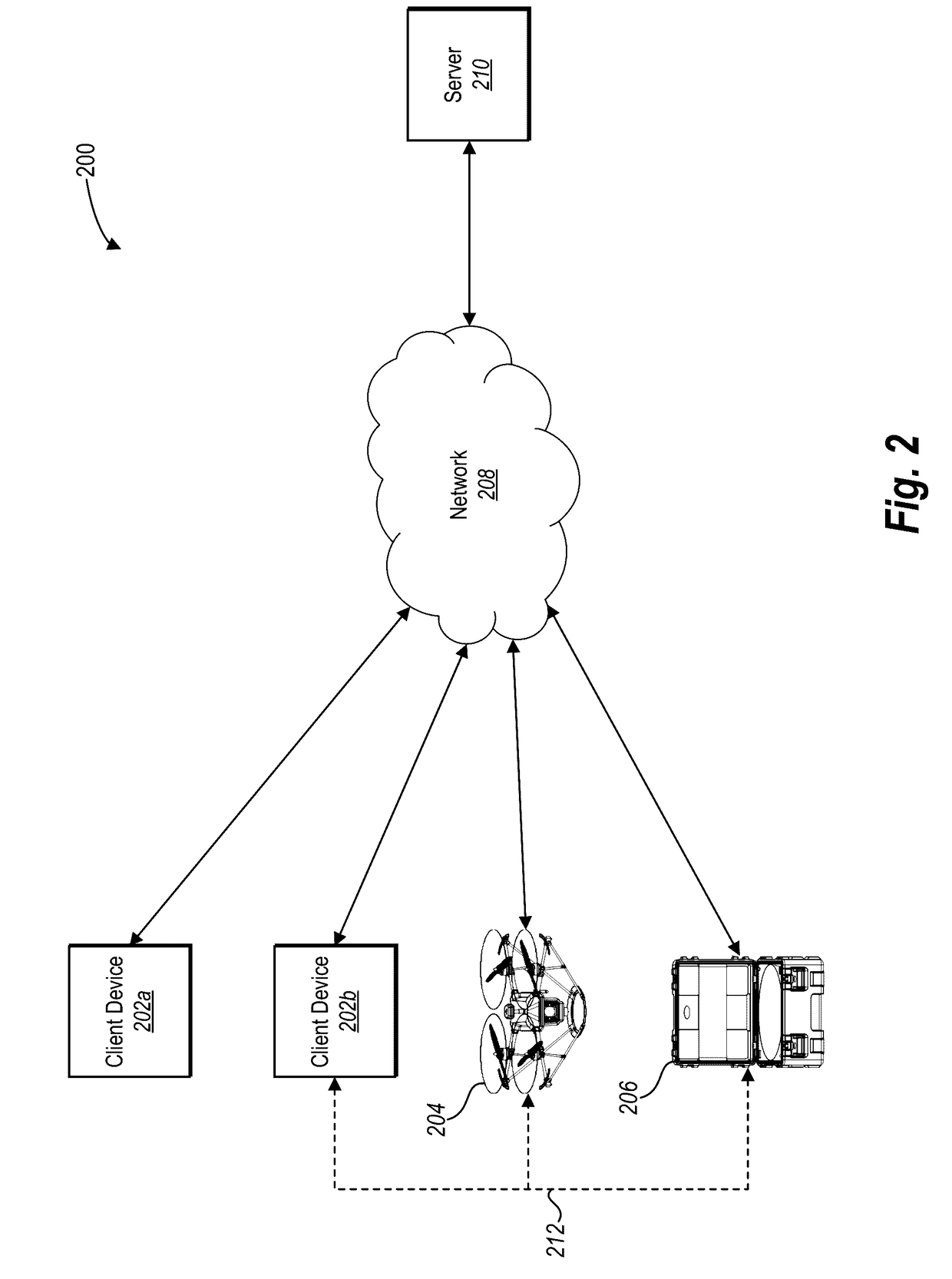
[0039]The present disclosure includes various embodiments and features of a mission generation system and corresponding processes that produce mission plans for capturing aerial images of a target site by a UAV. In particular, in one or more embodiments the mission generation system generates flight legs for traversing a target site and identifies optimal or near-optimal connections between the flight legs utilizing one or more linking algorithms. The mission generation system can generate a flight path that remains within a mission boundary. Moreover, the mission generation system can incorporate the flight path into a mission plan for capturing aerial images of a target site utilizing a UAV.

[0040]For example, in one or more embodiments the mission generation system identifies a mission boundary defining a UAV flight area. Specifically, the mission generation system identifies a mission boundary that encompasses a target site for capturing a plurality of aerial images by a UAV. The...


PUM


Abstract

Systems and methods are disclosed for generating a digital flight path within complex mission boundaries. In particular, in one or more embodiments, systems and methods generate flight legs that traverse a target site within mission boundaries. Moreover, one or more embodiments include systems and methods that utilize linking algorithms to connect the generated flight legs into a flight path. Moreover, one or more embodiments include systems and methods that generate a mission plan based on the flight path. In one or more embodiments, the generated mission plan enables a UAV to traverse a flight area within mission boundaries and capture aerial images with regard to the target site.

Description

CROSS-REFERENCE TO RELATED APPLICATIONS[0001]The present application is a continuation of U.S. patent application Ser. No. 14 / 887,954, filed on Oct. 20, 2015. The aforementioned application is hereby incorporated by reference in its entirety.BACKGROUND[0002]1. Technical Field[0003]One or more embodiments of the present disclosure relate generally to digital mission plans for unmanned aerial vehicles (UAVs). More specifically, one or more embodiments of the present disclosure relate to systems and methods for generating a digital mission plan for capturing aerial images within a mission boundary utilizing a UAV.[0004]2. Background and Relevant Art[0005]Individuals and businesses increasingly utilize digital aerial images to capture information regarding target sites. Indeed, in light of advances in unmanned aerial vehicles (UAVs), digital aerial photography has become increasingly affordable, and therefore accessible, for individual, industrial, and commercial applications. For insta...

Claims


Application Information

Patent Timeline
Patent Type & Authority Applications(United States)
IPC IPC(8): G08G5/00G05D1/00B64C39/02
CPCG08G5/0034B64C39/024B64C2201/123B64C2201/127G05D1/0094G08G5/006G08G5/0069G08G5/0086G05D1/0202B64U2101/30
Inventor TENG, YIFEICHEN, DAVIDSTUART, PATRICK
Owner SKYCATCH
Why Eureka
Try Eureka