
Money handling apparatus and money handling method

Inactive Publication Date: 2011-03-03
GLORY KOGYO KK
View PDF5 Cites 0 Cited by
  • Summary
  • Abstract
  • Description
  • Claims
  • Application Information

AI Technical Summary

Benefits of technology

[0005]The present invention was made in light of the above problem, and therefore it is an object of this invention to provide a money handling apparatus and money handling method, respectively capable of enhancing the operability of the operation / display unit. Namely, according to the money handling apparatus and money handling method of this invention, once the operator sets existence or nonexistence of display, for each operation key to be displayed on the operation / display unit, such as the touch panel or the like, only the operation key or keys set to be displayed, among the various operation keys, can be displayed on the operation / display unit, while each display position and size of such displayed operation key or keys can be changed so as to facilitate each operation of such operation key or keys performed by the operator, thereby significantly enhancing the operability of the operation / display unit.
[0007]According to this money handling apparatus, the operation / display unit can serve to display thereon the count result on the money as well as display thereon a part or all of the various operation keys, based on the existence or nonexistence of display, contents of display, display-position information and one or more conditions of display, for the various operation keys, respectively stored in the memory unit. Further, the existence or nonexistence of display for the various operation keys can be set by the setting unit and the display-position information on each operation key can be calculated, based on one or more conditions of display stored in the memory unit, for only the operation key or keys, among the various operation keys, respectively set, by the setting unit, to be displayed on the operation / display unit. In addition, the operation / display unit is controlled to display thereon the count result on the money as well as to display thereon each operation key set to be displayed, in the display position and size based on the display-position information on each operation key. Therefore, once the operator sets the existence or nonexistence of display, for each operation key to be displayed on the operation / display unit, only the operation key or keys set to be displayed, among the various operation keys, can be displayed on the operation / display unit, while the display position and size of each displayed operation key can be changed so as to facilitate the operation of each key performed by the operator, thereby significantly enhancing the operability of the operation / display unit.
[0019]According to this money handling method, once the operator sets the existence or nonexistence of display, for each operation key to be displayed on the operation / display unit, only the operation key or keys set to be displayed, among the various operation keys, can be displayed on the operation / display unit, while the display position and size of each operation key can be changed so as to facilitate the operation of each key performed by the operator, thereby significantly enhancing the operability of the operation / display unit.

Problems solved by technology

Therefore, when the operation key displayed on the touch panel is pushed, the operator may tend to inadvertently push two operation keys, at a time, or otherwise may tend to accidentally push another operation key located adjacent to a target operation key.
In addition, in the case only the operation key or keys set to be displayed, among the various operation keys, are displayed on the touch panel, if such operation key or keys are located at or around peripheral or corner portions of the touch panel, it is likely to be difficult for the operator to accurately push each of such operation keys.

Method used


Image

  • Money handling apparatus and money handling method
  • Money handling apparatus and money handling method
  • Money handling apparatus and money handling method

Examples


Embodiment Construction

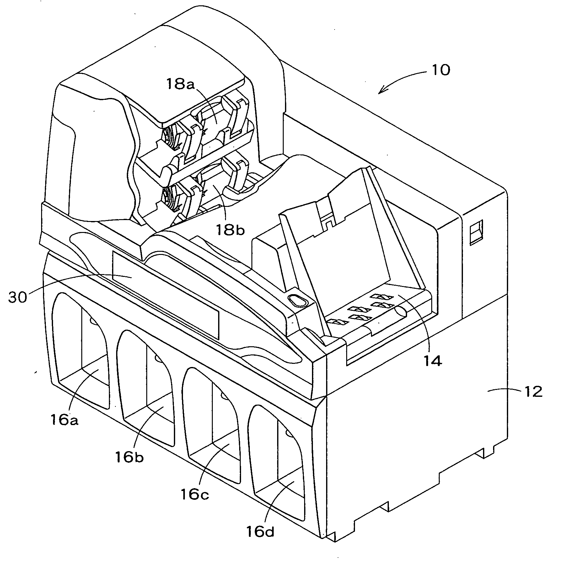
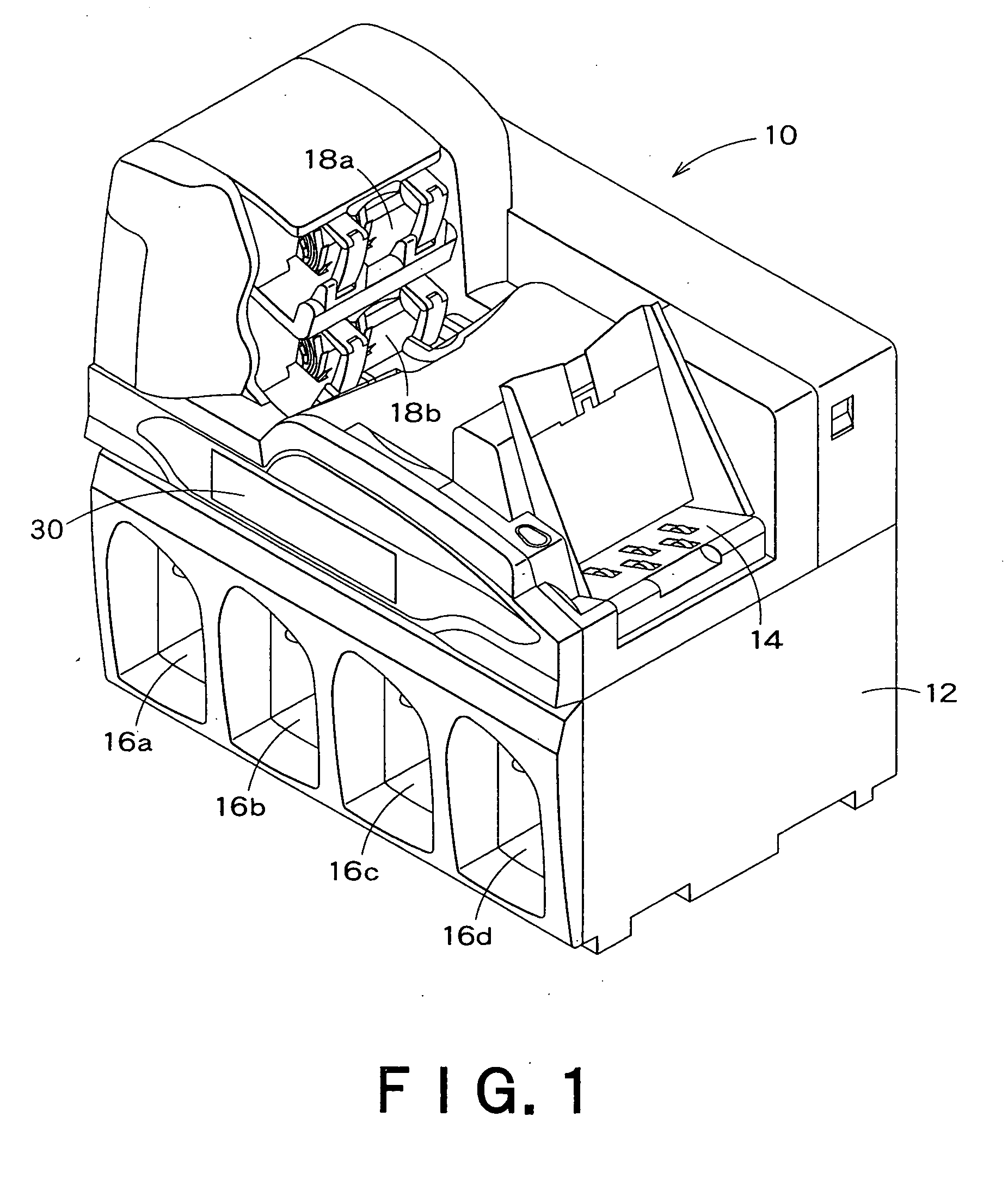
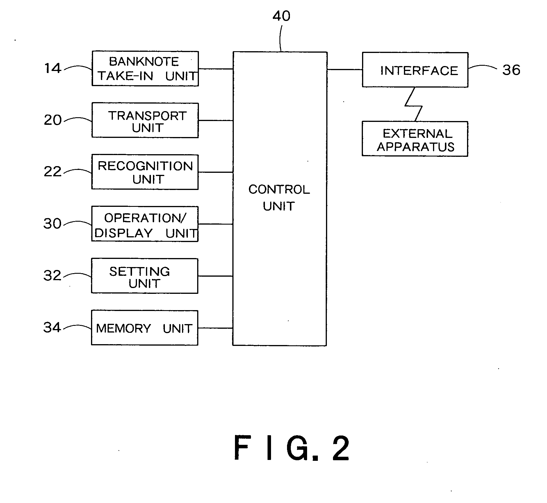
[0035]Hereinafter, one embodiment of the present invention will be described with reference to the drawings. FIGS. 1 through 12 are provided herein for respectively illustrating the banknote handling apparatus related to this embodiment. Of these drawings, FIG. 1 is the perspective view showing the construction of the banknote handling apparatus related to this embodiment, and FIG. 2 is the block diagram illustrating the control system of the banknote handling apparatus shown in FIG. 1. FIG. 3 is the flow chart showing the operation for changing the display layout of the various operation keys on the operation / display unit of the banknote handling apparatus shown in FIG. 1 or the like. FIGS. 4 through 9 are provided for respectively illustrating the contents of display on the operation / display unit of the banknote handling apparatus shown in FIG. 1 or the like. FIG. 10 is the table for illustrating the conditions of display and existence or nonexistence of display, for the various o...


PUM


Abstract

A money handling apparatus 10 includes: an operation / display unit 30 configured to display thereon a count result on money as well as configured to display thereon a part or all of various operation keys, based on existence or nonexistence of display, contents of display, display-position information and one or more conditions of display, for the various operation keys, respectively stored in a memory unit 34; and a setting unit 32 configured to set the existence or nonexistence of display for each operation key. A control unit of this money handling apparatus 10 calculates the display-position information on each operation key, based on one or more conditions of display stored in the memory unit 34, for only the operation key or keys, among the various operation keys, respectively set, by the setting unit 32, to be displayed on the operation / display unit 30, and then makes the operation / display unit 30 display thereon the count result on the money as well as display thereon each operation key set to be displayed, in the display position and size based on the display-position information on the operation key.

Description

FIELD OF THE INVENTION[0001]The present invention relates to a money handling apparatus including an operation / display unit, such as a touch panel or the like and a money handling method, and particularly relates to the money handling apparatus and money handling method, respectively capable of enhancing the operability of the operation / display unit.BACKGROUND OF THE INVENTION[0002]The money handling apparatus, which is used for handling money and includes the touch panel provided to an outer surface of its casing, has been known. In general, this touch panel is adapted for displaying thereon a count result on the money as well as displaying thereon various operation keys, such as a start key, a stop key, an accept key, a clear key, numeric keys and the like. With this touch panel, when a user pushes a certain operation key, among the various operation keys respectively displayed on the touch panel, an instruction corresponding to this operation key is sent to a control unit of the ...

Claims


Application Information

Patent Timeline
IPC IPC(8): G06F7/00G07D11/00
CPCG07D11/0084G07D11/0072G07D11/34G07D11/50
Inventor UESAKA, SADAAKISUDO, TERUOKOBAYASHI, KEISHI
Owner GLORY KOGYO KK
Learn More