Rear-focus zoom lens device and video camera

Inactive Publication Date: 2005-06-28
SONY CORP
View PDF7 Cites 3 Cited by
  • Summary
  • Abstract
  • Description
  • Claims
  • Application Information

AI Technical Summary

Benefits of technology

[0014]Accordingly, it is an object of the present invention to provide a rear-focus zoom lens device which can provide the same operability as a front-focus zoom lens device which is often used in business video cameras without using a clutch mechanism, and a video camera including the rear-focus zoom lens device.

Problems solved by technology

Therefore, provision of an auto-focusing function for controlling the focusing lens by an electric operation results in problems, such as an increase in the size of an actuator and an increase in power consumption.
Consequently, the front-focus zoom lens device is not necessarily a suitable zoom lens device.
Consequently, the operation ends of the zoom ring and the focus ring cannot be determined.
In a business video camera which requires a complicated image representation by, for example, repeating zooming within the same range by the rear-focus zoom lens device having this disadvantage, the fact that the zooming position is a relative position which changes each time focusing is carried out is a critical disadvantage.
This is one of the major reasons why the rear-focus zoom lens device is not conventionally accepted for use in video cameras.
In the related clutch mechanism, however, when the zoom function is set to the manual mode once, if it becomes necessary to carry out flange back adjustment or angle-of-view correction by zooming due to thermal expansion / contraction of the entire lens barrel or due to an auto-focusing function, electrical correction cannot be carried out.
Therefore, when an operator tries to carry out focusing, he / she may touch the zoom ring, or the zoom ring may move by, for example, slight vibration when it is installed in a vehicle.
When focusing is carried out while the angle of view is deliberately fixed, such as in time-lapse shooting or animation shooting, the operator may accidentally touch the zoom ring and unconsciously change the angle of view, as a result of which an image cannot be used.
Even if a related zoom lens device can store the position, it does not have a mechanism for fixing the position.

Method used


Image

  • Rear-focus zoom lens device and video camera
  • Rear-focus zoom lens device and video camera
  • Rear-focus zoom lens device and video camera

Examples


second embodiment

(2) Second Embodiment

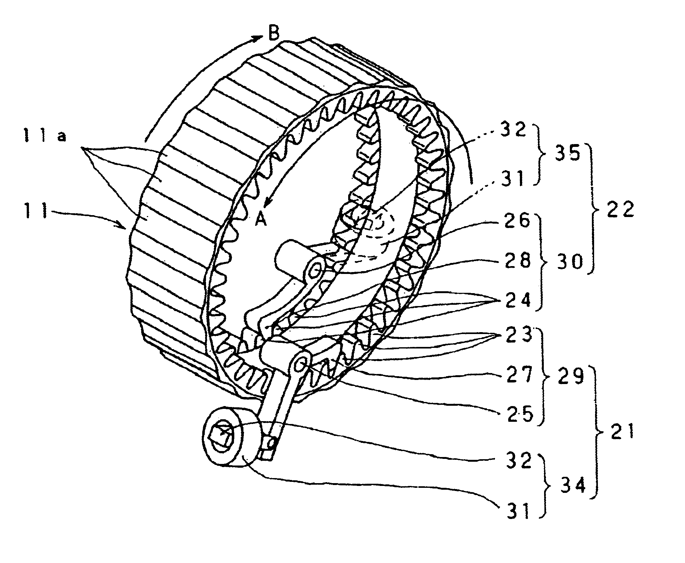
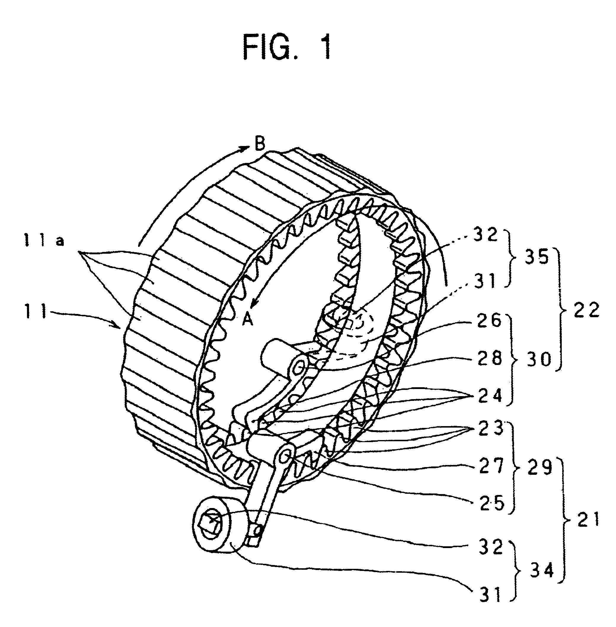
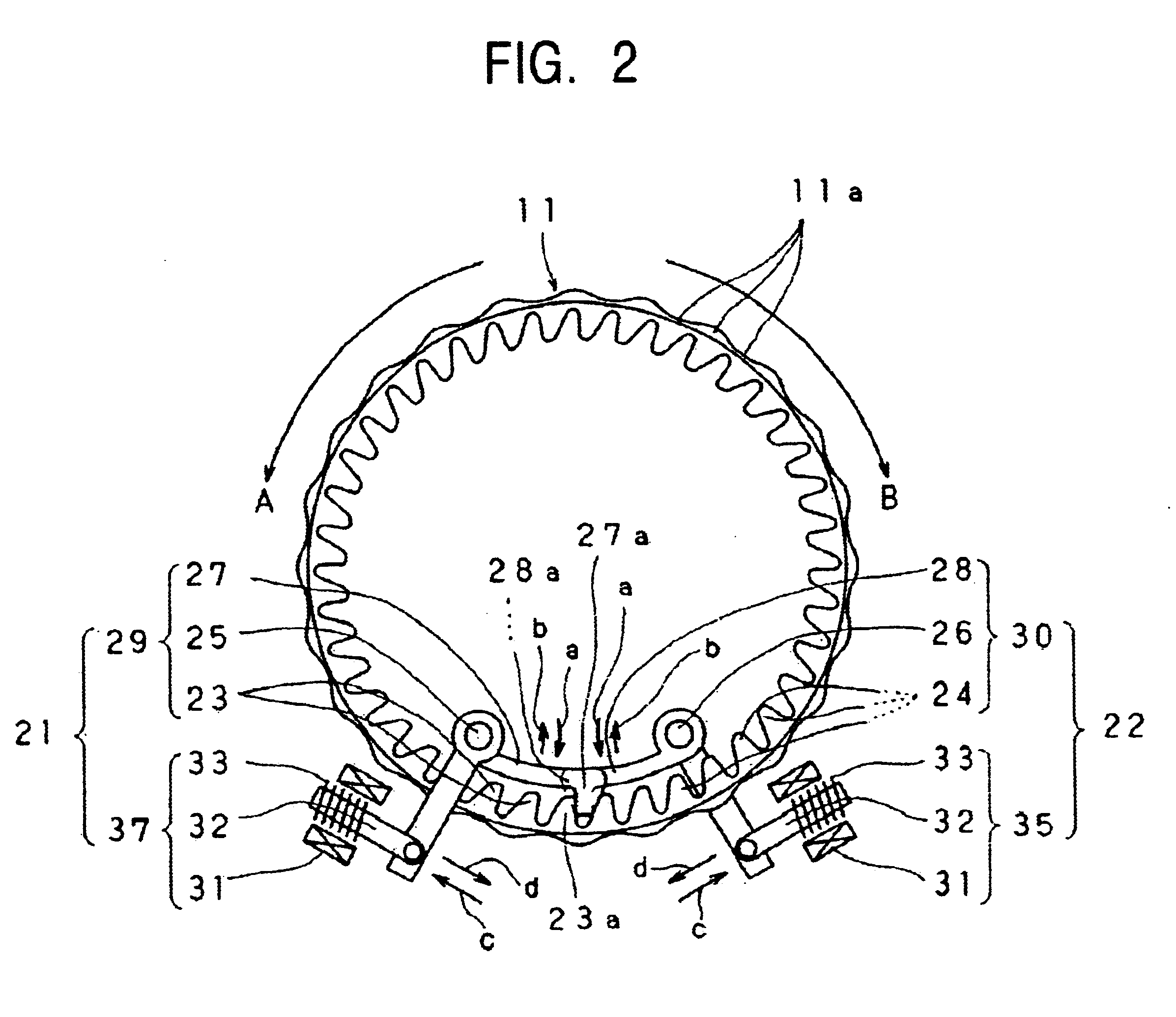
[0088]Next, a zoom lens device 1 of a second embodiment of the present invention will be given with reference to FIGS. 9 to 11. In this case, the aforementioned wide-angle direction rotation restricting means 21 and the telephoto direction rotation restricting means 22 are attached to the rotary ring 110 which rotates in response to the movement of the aforementioned zoom ring 11.

[0089]The wide-angle direction rotation restricting means 21 comprises a ratchet mechanism 29 and an actuator 34. The telephoto direction rotation restricting means 22 comprises a ratchet mechanism 30 and an actuator 35. The ratchet mechanism 29 comprises a ratchet pawl 23 and a ratchet pawl arm 27. The ratchet mechanism 30 comprises a ratchet pawl 24 and a ratchet pawl arm 28. The ratchet pawls 23 and 24 are disposed in an annular form along the entire outer periphery at respective ends of the rotary ring 110 in an axial direction. The ratchet pawl arms 27 and 28 are disposed at the ou...

third embodiment

(3) Third Embodiment

[0094]Next, a description of a zoom lens device 1 of a third embodiment of the present invention will be given with reference to FIGS. 12 to 17. In this case, a wide-angle direction stepless rotation restricting means 210 and a telephoto direction stepless rotation restricting means 220 for restricting the rotation at stepless positions on the circumference of a zoom ring 11 are formed as the wide-angle direction rotation restricting means 21 and the telephoto direction rotation restricting means 22 for the zoom ring 11.

[0095]The wide-angle direction stepless rotation restricting means 210 and the telephoto direction stepless rotation restricting means 220 comprise, for example, respective roller compression surfaces 61 and 62, respective unidirectional rotation compression rollers 63 and 64, respective compression arms 67 and 68, and respective actuators 72 and 73. The roller compression surfaces 61 and 62 are smooth surfaces formed at the inner peripheral surfa...


PUM


Abstract

A rear-focus zoom lens device includes a wide-angle direction rotation restricting unit and a telephoto direction rotation restricting unit for separately restricting rotations of a zoom ring in a wide-angle direction and a telephoto direction and for separately canceling the restricting operations at any rotational positions of the zoom ring in the wide-angle direction and the telephoto direction, respectively, when rotating the zoom ring in the wide-angle direction and the telephoto direction, respectively.

Description

BACKGROUND OF THE INVENTION[0001]1. Field of the Invention[0002]The present invention relates to the technical field of a rear-focus zoom lens device for carrying out zooming by a zooming lens, which is a combination lens, disposed at an end of a lens barrel, and for carrying out focusing by a focusing lens, which is a combination lens, disposed rearward of the zooming lens. The present invention also relates to the technical field of a video camera including the rear-focus zoom lens device.[0003]2. Description of the Related Art[0004]As is widely known, two types of zoom lens devices are used in, for example, video cameras. They are a front-focus zoom lens device and a rear-focus zoom lens device. In the front-focus zoom lens device, focusing is carried by a focusing lens, which is a combination lens, disposed at an end of a lens barrel, and zooming is carried out by a zooming lens, which is a combination lens, disposed rearward of the focusing lens. In the rear-focus zoom lens dev...

Claims


Application Information

Patent Timeline
IPC IPC(8): G02B7/10H04N5/225
CPCG02B7/10
Inventor TERADA, HIROTSUGU
Owner SONY CORP
Why Eureka
Try Eureka