Medical image display system and medical image display apparatus

Inactive Publication Date: 2019-06-27
KONICA MINOLTA INC
View PDF1 Cites 0 Cited by
  • Summary
  • Abstract
  • Description
  • Claims
  • Application Information

AI Technical Summary

Benefits of technology

The patent aims to improve the visibility and usability of medical images displayed on a screen. This results in better quality images that are easier to read and interpret.

Problems solved by technology

The techniques disclosed in JP 2016-123584 A and JP 2017-074213 A, however, includes a problem of degradation of visibility due to a state where the view of the medical image is hidden by a finger or a hand because of operation on the medical image displayed on the touch panel.
In addition, since operation uses almost a whole region on the touch panel, it is not easy to operate with a single hand with a relatively large terminal such as a tablet terminal.

Method used

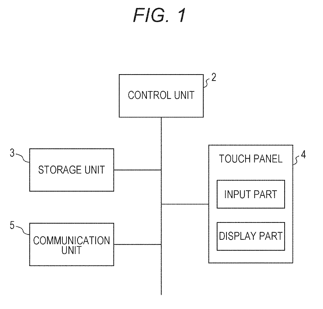

Image

  • Medical image display system and medical image display apparatus
  • Medical image display system and medical image display apparatus
  • Medical image display system and medical image display apparatus

Examples


configuration example 1

[0096]As illustrated in FIG. 11 to FIG. 14, a plurality of small regions 20 and 21 in the present configuration example is arranged on the display screen of the touch panel 4.

[0097]While the present configuration example uses a configuration in which the two small regions 20 and 21 are arranged on the display screen, three or more small regions may be provided, and the number is not particularly limited.

[0098]The plurality of small regions 20 and 21 is arranged at positions along the edge portions of the display screen of the touch panel 4. More specifically, one small region 20 in the present configuration example is arranged at one corner on the lower side of the four corners of the display screen, while the other small region 21 is arranged at the other corner on the lower side of the four corners of the display screen.

[0099]Gestures onto such small regions 20 and 21 can be registered from a gesture registration screen 30A as illustrated in FIG. 12. Similarly to the above-describ...

configuration example 2

[0107]As illustrated in FIG. 15, a small region 22 in the present configuration example corresponds to a whole region in which no medical image is displayed, among the display screen of the touch panel 4. Within this small region 22, a range of an input region 22a can be defined with a portion touched by the user as a starting point. In other words, in the present configuration example, portions around the position touched by the user are set to be the input region 22a into which gestures can be input, among the portions (small regions 22) where no medical image is displayed on the display screen.

[0108]With this configuration, it is possible to change the position of the input region 22a in which the gesture can be input in accordance with a medical image displayed in the image display region 10, making it possible to enhance convenience and operability.


PUM


Abstract

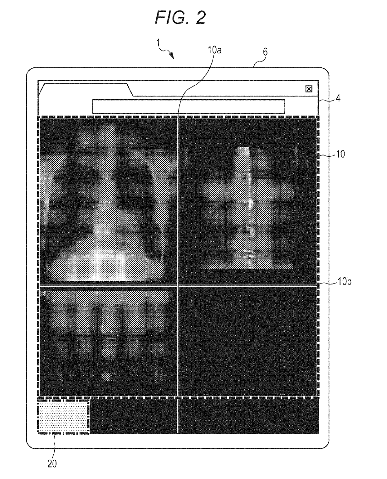
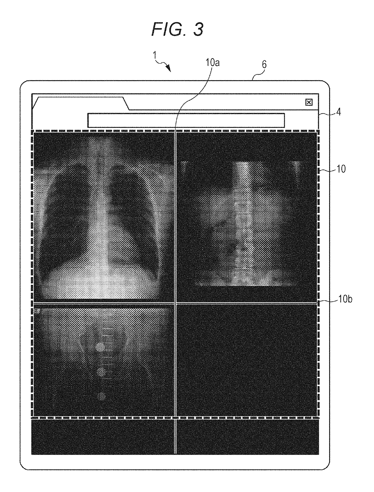
A medical image display system includes a medical image display apparatus that displays a medical image on a display screen of a touch panel, the medical image display system being capable of changing a display mode of the medical image displayed on the display screen on the basis of screen contact operation on the display screen, wherein the display screen includes: an image display region that displays the medical image; and a small region being a region smaller than the image display region and arranged at a position where the medical image is not displayed, and a display mode of the image display region is set so as to change on the basis of the screen contact operation in the small region.

Description

CROSS REFERENCE TO RELATED APPLICATION[0001]The present application claims priority under 35 U.S.C. § 119 to Japanese patent Application No. 2017-247215, filed on Dec. 25, 2017, is incorporated herein by reference in its entirety.BACKGROUNDTechnological Field[0002]The present invention relates to a medical image display system and a medical image display apparatus.Description of the Related Art[0003]There is a known medical image display apparatus capable of changing a display mode of a medical image displayed on a touch panel on the basis of an instruction on a touch panel such as a smartphone or a tablet terminal.[0004]JP 2016-123584 A discloses a technique capable of performing a simulation of first defining a first point and a second point designated by an operator on a touch panel of a display terminal and then dividing an anatomical structure as a subject into a plurality of parts by using a line defined by the first and second points as a cutting reference line.[0005]JP 2017-...

Claims


Application Information

Patent Timeline
IPC IPC(8): G06F3/0481G06F3/0488G06F3/0484A61B90/00
CPCG06F3/0481G06F3/04883G06F3/0484A61B90/37G06F2203/04803G06T11/60G06T2210/41A61B2090/372G06T2200/24
Inventor SUGEGAYA, NAOTOSHI
Owner KONICA MINOLTA INC
Why Eureka
Try Eureka