Electric power tool

Inactive Publication Date: 2009-10-15
MATSUSHITA ELECTRIC WORKS LTD
View PDF17 Cites 3 Cited by
  • Summary
  • Abstract
  • Description
  • Claims
  • Application Information

AI Technical Summary

Benefits of technology

[0012]The push operation grooves may be inclined at an obtuse angle with respect to the slide operation groove. In this case, the operation lever moves, when pushed, in the direction inclined at an obtuse angle with respect to the slide operation groove and not in the direction perpendicular to the slide operation groove. Therefore, the transition from the pushing operation to the sliding operation occurs smoothly, thereby enhancing the operability of the operation lever.
[0013]The speed changing unit may further includes a resilient member for biasing the projection portion against the guide portion in a direction to restrain the movement of the operation lever and a restraint releasing unit for moving the projection portion to permit the movement of the operation lever when the operation lever is pushed. In this case, use of the resilient body and the restraint releasing unit makes it possible to bring the operation lever from a movement-restrained state into a movement-permitted state in response to the pushing operation of the operation lever. This ensures that the transition from the pushing operation to the speed-changing sliding operation occurs in a smoother manner.
[0014]The operation detector unit may be designed to detect the operation lever when the operation lever is in a generally middle position between a non-pushed position and a pushed position. In this case, if the operation lever is not pushed down by a predetermined amount, the operation detector unit fails to detect the pushing operation of the operation lever. This makes it possible to prevent an erroneous operation of the electric power tool which would otherwise occur when the operation lever is touched inadvertently.
[0015]The operation lever may include an interrupter plate having a predetermined length in the speed changing direction, the o

Problems solved by technology

This may sometimes cause trouble to the electric power tool.
More specifically, if the gear reduction ratio is changed with the operation lever 105 during the course of work, namely if the gear 102a of the speed reducer unit 102 is shifted when in rotation, the mutually engageable gears may m

Method used


Image

  • Electric power tool
  • Electric power tool
  • Electric power tool

Examples


Example

[0042]Hereinafter, an embodiment of the present invention will be described with reference to the accompanying drawings which form a part hereof.

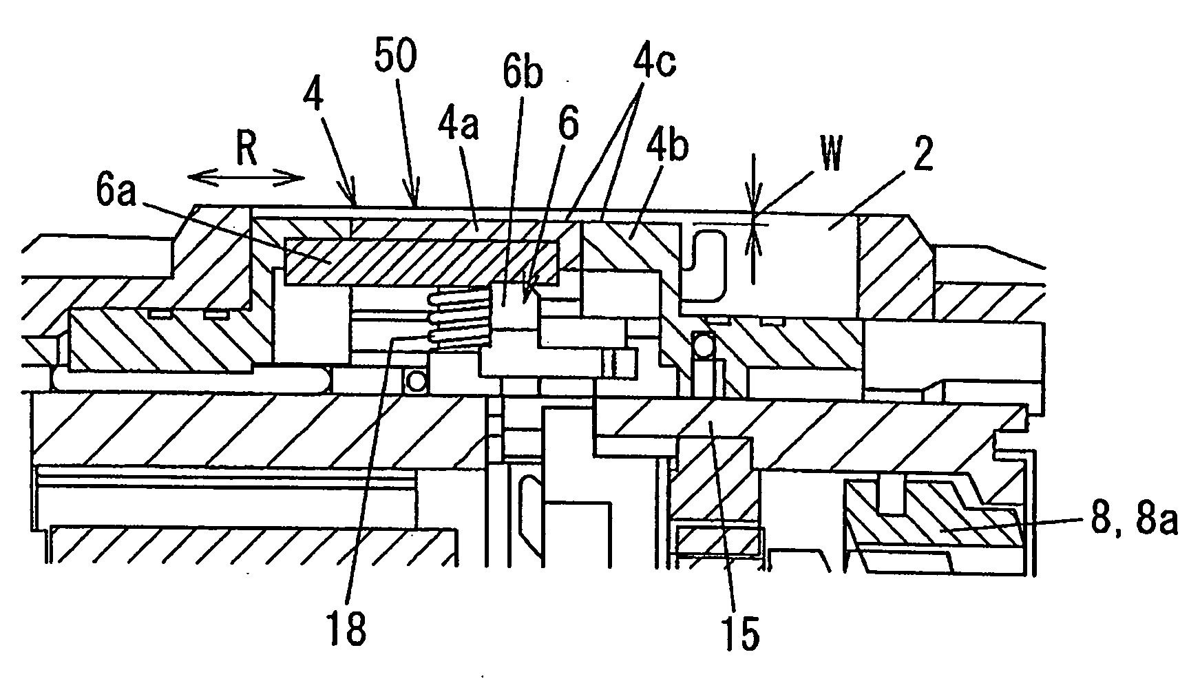
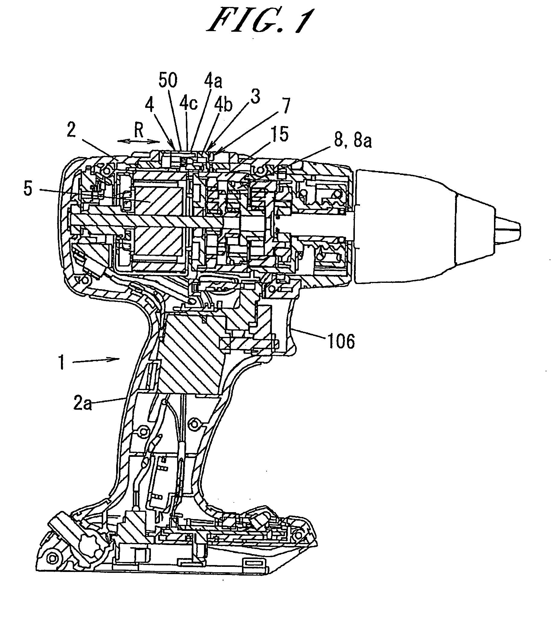
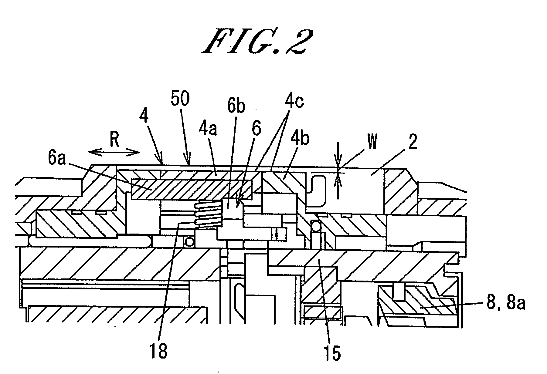
[0043]Referring to FIG. 1, the electric power tool 1 of the present embodiment essentially includes a motor 5 as a driving power source, a speed reducer unit 8 arranged to deliver the rotational power of the motor 5 and provided with two or more gears 8a, a driving unit arranged to deliver the rotational power of the speed reducer unit 8 to a tip end tool, a bearing unit for rotatably supporting the driving unit, a housing 2 arranged to accommodate the motor 5, the speed reducer unit 8, the driving unit and the bearing unit therein and provided with a handle portion 2a, and a speed changing mechanism 3 for changing the gear reduction ratio of the speed reducer unit 8, the speed changing mechanism 3 being arranged in a position where it can be operated outside the housing 2. In FIG. 1, reference numeral 106 designates a power switch for swit...


PUM


Abstract

An electric power tool includes a motor, a speed reducer unit arranged to deliver the rotational power of the motor and provided with gears, a housing arranged to accommodate the motor and the speed reducer unit, and a speed changing unit for changing a gear reduction ratio of the speed reducer unit. The speed changing unit is arranged in such a position as to be operable outside the housing. The speed changing unit includes an operation lever slidingly operable in a speed changing direction when pushed, an operation detector unit for detecting the operation lever to control electric power supplied to the motor, a shift unit for changing the gear reduction ratio of the speed reducer unit in response to sliding movement of the operation lever, and a slide restraint unit for restraining the sliding operation of the operation lever until the operation detector unit detects the operation lever.

Description

FIELD OF THE INVENTION[0001]The present invention relates to an electric power tool, such as a drill driver, a disc saw or the like, which has a speed changing function performed by a speed reduction mechanism.BACKGROUND OF THE INVENTION[0002]In general, there are known electric power tools that have a speed changing function with a view to enhance work efficiency (see, e.g., Japanese Patent Laid-open Publication No. 63-101545).[0003]One example of the electric power tools is shown in FIG. 15. This electric power tool includes a motor 101 as a driving power source, a speed reducer unit 102 for delivering the rotational power of the motor 101 at a reduced speed, a drive unit (not shown) for delivering the rotational power of the speed reducer unit 102 to a tip end tool, a resin-made housing 104 provided with a handle portion 104a and arranged to contain the motor 101 and the speed reducer unit 102 therein, an operation lever 105 and a shift unit 105a, both of which serve as a speed c...

Claims


Application Information

Patent Timeline
IPC IPC(8): G05G5/08
CPCY10T74/20098B25F5/001
Inventor INAGAKI, KENICHIROSEKINO, FUMIAKIYAMADA, YUTAKA
Owner MATSUSHITA ELECTRIC WORKS LTD
Why Eureka
Try Eureka