Adjustable partial annuloplasty ring and mechanism therefor

a partial annuloplasty and annuloplasty ring technology, applied in the field of valve repair, can solve the problems of reducing cardiac output, increasing total stroke volume, and ultimate weakening of the left ventricle, and achieve the effect of facilitating the contracting of the annuloplasty structur

Active Publication Date: 2010-06-24
VALTECH CARDIO LTD
View PDF99 Cites 282 Cited by
  • Summary
  • Abstract
  • Description
  • Claims
  • Application Information

AI Technical Summary

Benefits of technology

[0028]In some embodiments of the present invention, apparatus is provided comprising an adjustable annuloplasty structure configured to repair a dilated mitral valve of a patient. At least a portion of the annuloplasty structure comprises a flexible, longitudinally-compressible segment (e.g., coiled structures, stent-like struts, or a braided mesh). The annuloplasty structure is shaped to define a lumen thereof that houses a flexible member, e.g., a contracting wire. The annuloplasty structure comprises a contracting mechanism which facilitates contracting of the annuloplasty structure. The contracting mechanism comprises a spool to which a first end of the flexible member is coupled. Typically, a second end of the flexible member is not coupled to the spool, but rather is coupled to a portion of the annuloplasty structure.

Problems solved by technology

Mitral regurgitation of blood from the left ventricle into the left atrium results in increased total stroke volume and decreased cardiac output, and ultimate weakening of the left ventricle secondary to a volume overload and a pressure overload of the left atrium.

Method used


Image

  • Adjustable partial annuloplasty ring and mechanism therefor
  • Adjustable partial annuloplasty ring and mechanism therefor
  • Adjustable partial annuloplasty ring and mechanism therefor

Examples


Embodiment Construction

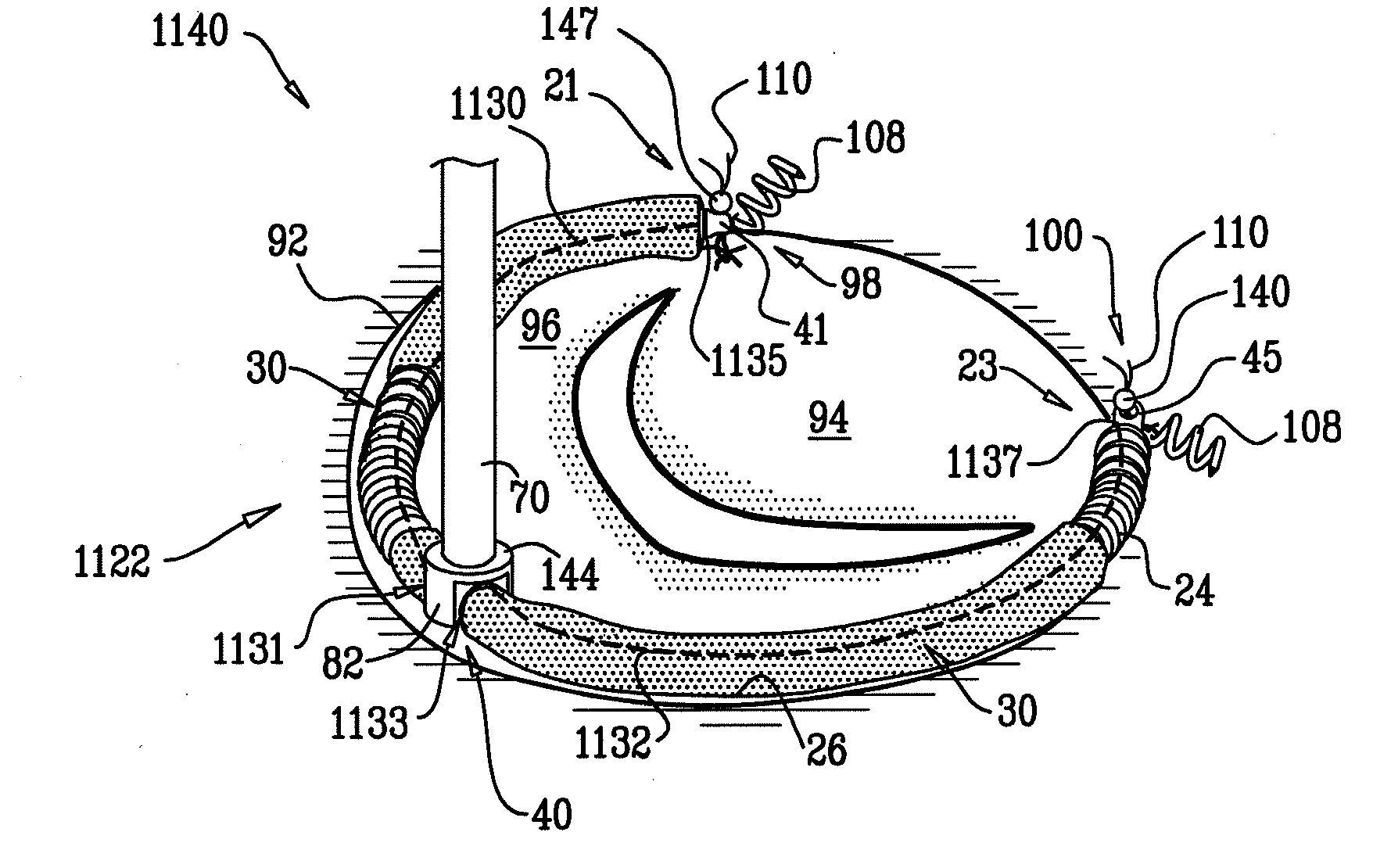
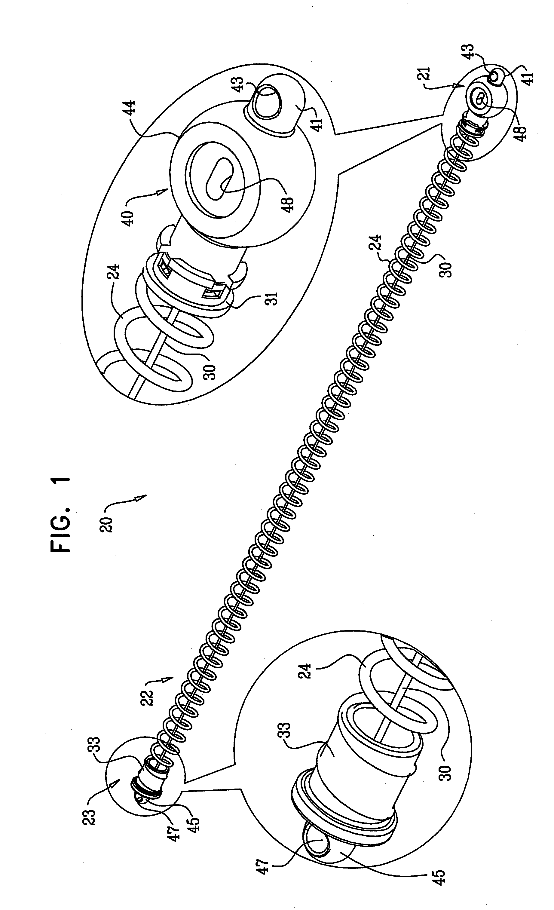
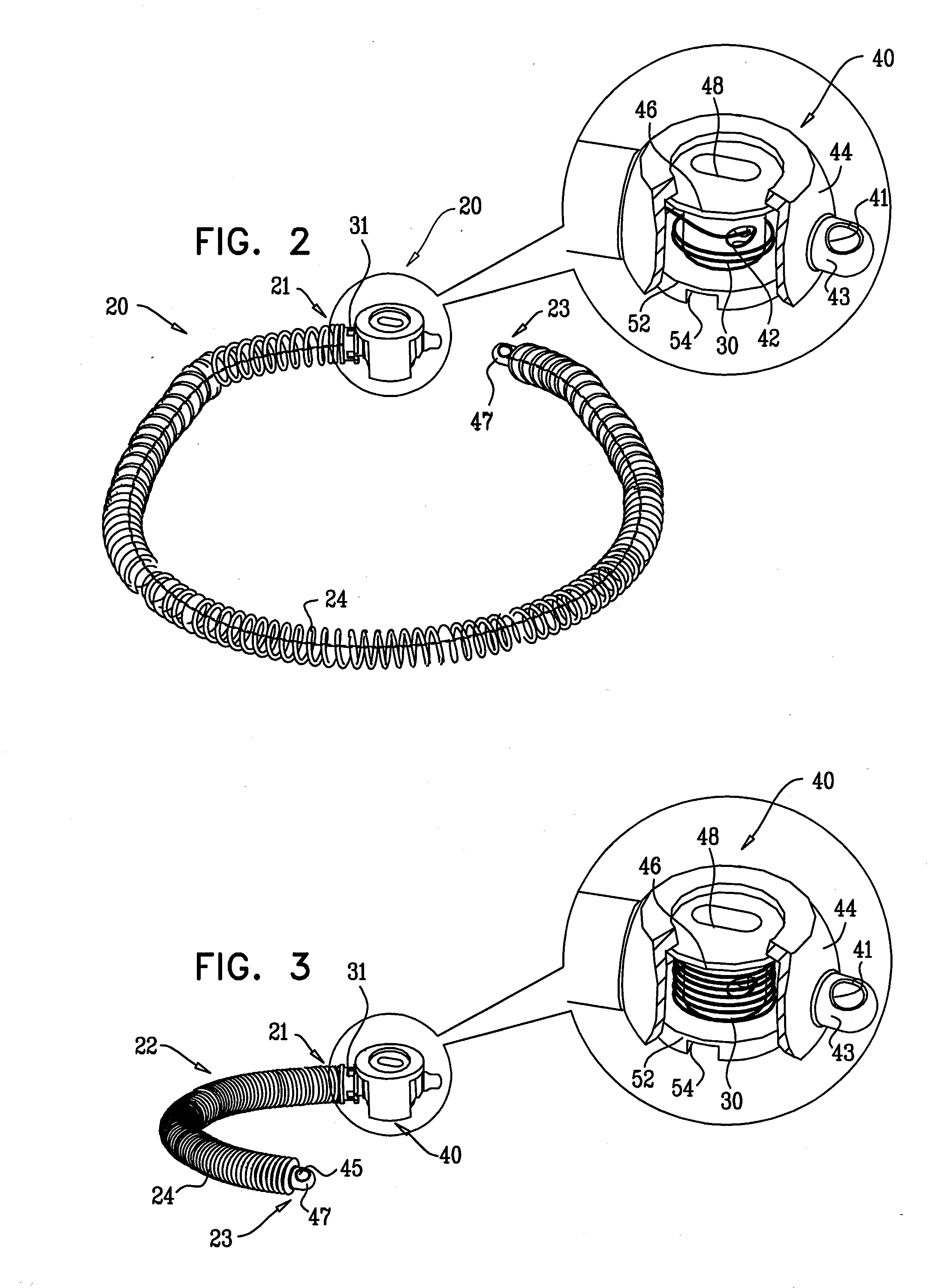
[0185]Reference is now made to FIGS. 1-3, which are schematic illustrations of a system 20 for repairing a dilated annulus of a subject comprising an implant structure, e.g., an annuloplasty structure 22, comprising a body portion 24, a flexible member 30, and a contracting mechanism 40, in accordance with an embodiment of the present invention. FIG. 1 shows structure 22 in a resting state thereof in which structure 22 defines a linear, elongate structure having a longitudinal axis thereof. At least a portion, e.g., the entirety, of body portion 24 comprises a compressible material, e.g., a coiled element, as shown by way of illustration and not limitation. For example, body portion 24 may comprise stent-like struts, or a braided mesh. Typically, body portion 24 defines a lumen along the longitudinal axis of structure 22 which houses flexible member 30. Flexible member 30 comprises a wire, a ribbon, a rope, or a band, comprising a flexible metal. Flexible member 30 is coupled at a f...


PUM


Abstract

Apparatus is provided that is configured to be implanted in a body of a subject, comprising an implant structure having first and second portions thereof, a spool coupled to the implant structure in a vicinity of the first portion thereof, and a flexible member coupled at a first end thereof to the spool, and not attached at a second end thereof to the spool. The flexible member, in response to rotation of the spool in a first direction thereof, is configured to be wound around the spool, and, responsively, to pull the second end of the flexible member toward the first end of the implant structure, and responsively to draw the first and second portions of the implant structure toward each other. Other embodiments are also described.

Description

CROSS-REFERENCES TO RELATED APPLICATIONS[0001]The present application is related to PCT Publication WO 06 / 097931 to Gross et al., entitled, “Mitral Valve treatment techniques,” filed Mar. 15, 2006, which is incorporated herein by reference.FIELD OF THE INVENTION[0002]The present invention relates in general to valve repair. More specifically, the present invention relates to repair of a mitral valve of a patient.BACKGROUND OF THE INVENTION[0003]Ischemic heart disease causes mitral regurgitation by the combination of ischemic dysfunction of the papillary muscles, and the dilatation of the left ventricle that is present in ischemic heart disease, with the subsequent displacement of the papillary muscles and the dilatation of the mitral valve annulus.[0004]Dilation of the annulus of the mitral valve prevents the valve leaflets from fully coapting when the valve is closed. Mitral regurgitation of blood from the left ventricle into the left atrium results in increased total stroke volume...

Claims


Application Information

Patent Timeline
Patent Type & Authority Applications(United States)
IPC IPC(8): A61F2/24
CPCA61B2017/0441A61B2017/0464A61F2250/0004A61F2/2466A61F2/2445A61B2017/0649A61F2/2448A61B17/068A61B17/072A61B2017/00243A61B2017/003A61F2220/0016A61F2250/0007
Inventor CABIRI, OZ
Owner VALTECH CARDIO LTD
Why Eureka
Try Eureka