Biomass fast pyrolysis system utilizing non-circulating riser reactor

a pyrolysis system and reactor technology, applied in the direction of fuels, combustible gas production, combustible gas purification/modification, etc., can solve the problems of high liquid and low char yield obtained

Inactive Publication Date: 2010-07-01
INNOVATIVE ENERGY GLOBAL
View PDF28 Cites 174 Cited by
  • Summary
  • Abstract
  • Description
  • Claims
  • Application Information

AI Technical Summary

Problems solved by technology

In particular, contrary to the prior art, both high liquid and low char yields are obtained.

Method used


Image

  • Biomass fast pyrolysis system utilizing non-circulating riser reactor
  • Biomass fast pyrolysis system utilizing non-circulating riser reactor
  • Biomass fast pyrolysis system utilizing non-circulating riser reactor

Examples


example 1

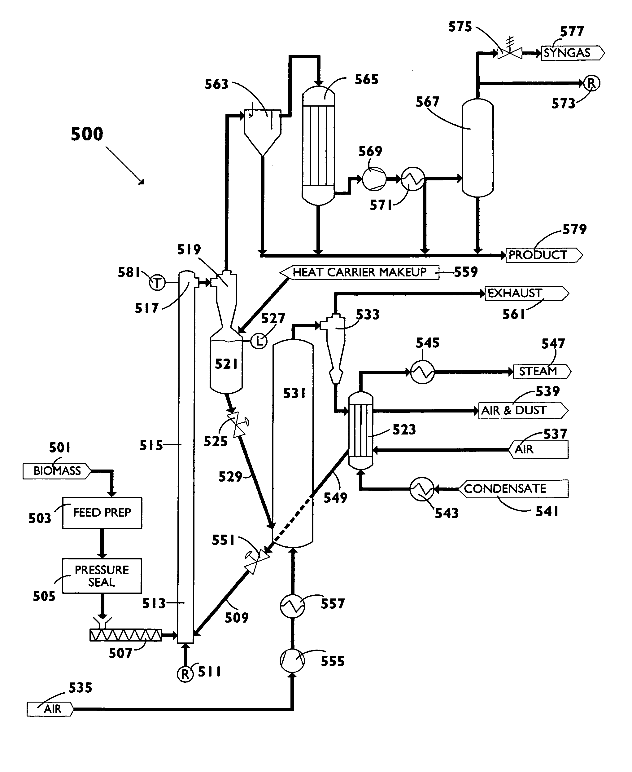
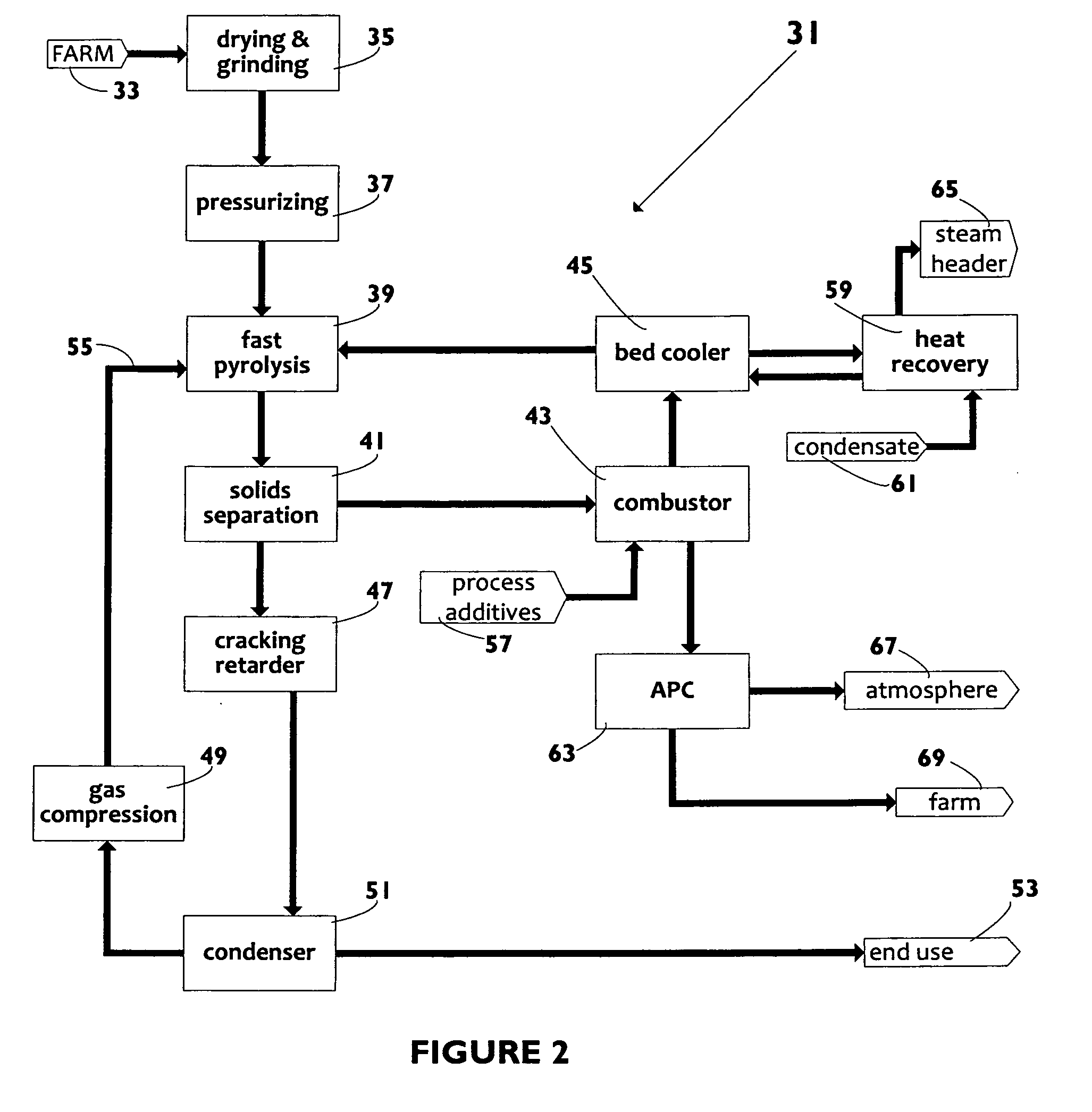
[0074]This example should be taken in conjunction with FIGS. 2,4, 5, 6 and 7, utilizing the physical structures and process steps set forth therein.

[0075]Filtercane biomass is farmed and harvested. Prior to entering the pyrolysis process steps, the biomass goes through the preparation processes of drying and pulverizing to create the dry powder material. Presses are needed if the biomass is wet or has high water content. Dryers and size reduction mills are utilized to reduce moisture content to preferably below 18% and 1 mm in size.

[0076]Once reduced to dry powder, the biomass feed needs to be pressurized to enter the reactor. Pressurization is achieved by screw feeder means with valving or sealing options to feed the biomass into the reactor under pressure.

[0077]The biomass feed enters the reactor, a non-circulating transport riser reactor of the type shown in FIG. 4 and described above, for fast pyrolysis (residence time under or well under 3 seconds, in some cases, less than 1 se...


PUM

PropertyMeasurementUnit
pressuresaaaaaaaaaa
operating pressureaaaaaaaaaa
operating temperatureaaaaaaaaaa

Abstract

A biomass fast pyrolysis system for conversion of biomass vegetation to synthetic gas and liquid fuels includes: a) a non-circulating riser reactor for pyrolysis of biomass vegetation feedstock utilizing a heat carrier, the non-circulating riser reactor being physically structured and adapted to have a rate of reaction of at least 8,000 biomass vegetation feedstock lbs / hr / ft2, utilizing a ratio of heat carrier to biomass vegetation feedstock of about 7:1 to about 11.5:1, the riser reactor having a base input region at its bottom, a central reaction region and an output region at its top, the riser reactor including a cyclone disengager at its output region for separation of pyrolysis resulting char and heat carrier from the pyrolysis product gases, the cyclone disengager having an output downcomer and an output upcomer, the cyclone disengager output downcomer being connected to and feeding into a side combustor unit, the riser reactor being a non-circulating riser reactor in that the heat carrier is not returned directly to the riser reactor from the cyclone disengager and travels first down the cyclone disengager output downcomer to the side combustor unit; and, b) the side combustor unit for combusting pyrolysis resultant char and reheating the heat carrier the side combustor having a heat carrier downcomer connected to the base input region of the riser reactor.

Description

BACKGROUND OF INVENTION[0001]a. Field of Invention[0002]The invention relates generally to a biomass rapid pyrolysis system wherein the system uniquely includes a non-circulating riser reactor with a specialized side combustor unit, and hence, a system that does not circulate the heat carrier directly through the disengager back to the riser reactor.[0003]b. Description of Related Art[0004]The following patents are representative of the field pertaining to the present invention:[0005]U.S. Pat. No. 7,374,661 B2 to Bridges et al. describes a method for thermally cracking a hydrocarbonaceous feed material using a combustion fuel fired furnace wherein at least part of the combustion fuel employed in the furnace is syngas.[0006]U.S. Pat. No. 7,241,323 B2 to Serio et al. describes a solid waste resource recovery in space is effected by pyrolysis processing, to produce light gases as the main products (CH2, H2, CO2, CO, H2O, NH2) and a reactive carbon-rich char as the main byproduct. Signi...

Claims


Application Information

Patent Timeline
Patent Type & Authority Applications(United States)
IPC IPC(8): C10J3/68B01J19/00C10J1/207
CPCC10G2300/1011C10L1/02C10J3/485C10J3/62C10J3/84C10K1/028C10K1/04C10B49/22C10B53/02C10C5/00C10G3/40C10G2300/1014C10G2300/1022C10J2300/0993C10J2300/1246Y02E50/14Y02P20/145Y02P30/20Y02E50/10
Inventor MILLS, KEVIN J.
Owner INNOVATIVE ENERGY GLOBAL
Why Eureka
Try Eureka