Foldable chair with forced air cooling system

a technology of forced air cooling and foldable chairs, which is applied in the field of foldable chairs, can solve the problems of providing passive air to the back of the individual, not affording the pleasure of event seating, etc., and achieves the effects of convenient transportation and operation, simple and economical manufacturing and assembly, and affordable cos

a technology of forced air cooling and foldable chairs, which is applied in the field of foldable chairs, can solve the problems of providing passive air to the back of the individual, not affording the pleasure of event seating, etc., and achieves the effects of convenient transportation and operation, simple and economical manufacturing and assembly, and affordable cos

US20100164256A1Inactive Publication Date: 2010-07-01SALISBURY KEITH B

Image

  • Foldable chair with forced air cooling system
  • Foldable chair with forced air cooling system
  • Foldable chair with forced air cooling system

Examples


Embodiment Construction

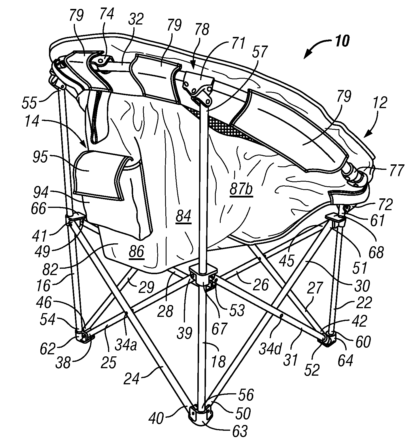
[0033]It is to be distinctly understood at the outset that the present invention shown in the drawings and described in detail in association with a compact, foldable chair that includes a forced air cooling system with a re-chargeable power source that is enclosed within a housing, is not intended to serve as a limitation upon the scope or teachings thereof, but is to be considered merely for the purpose of convenience of illustration of one example of its application.

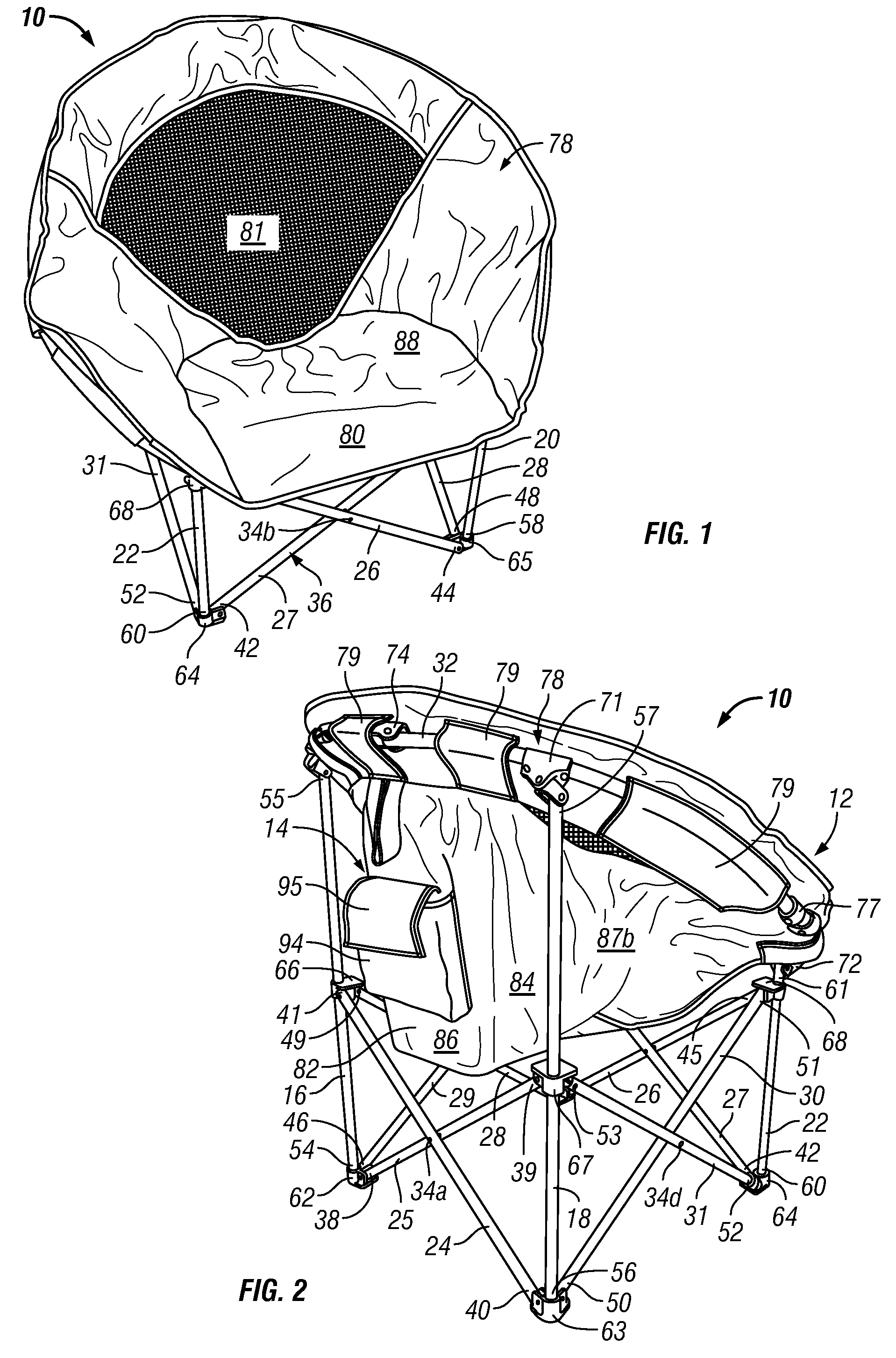
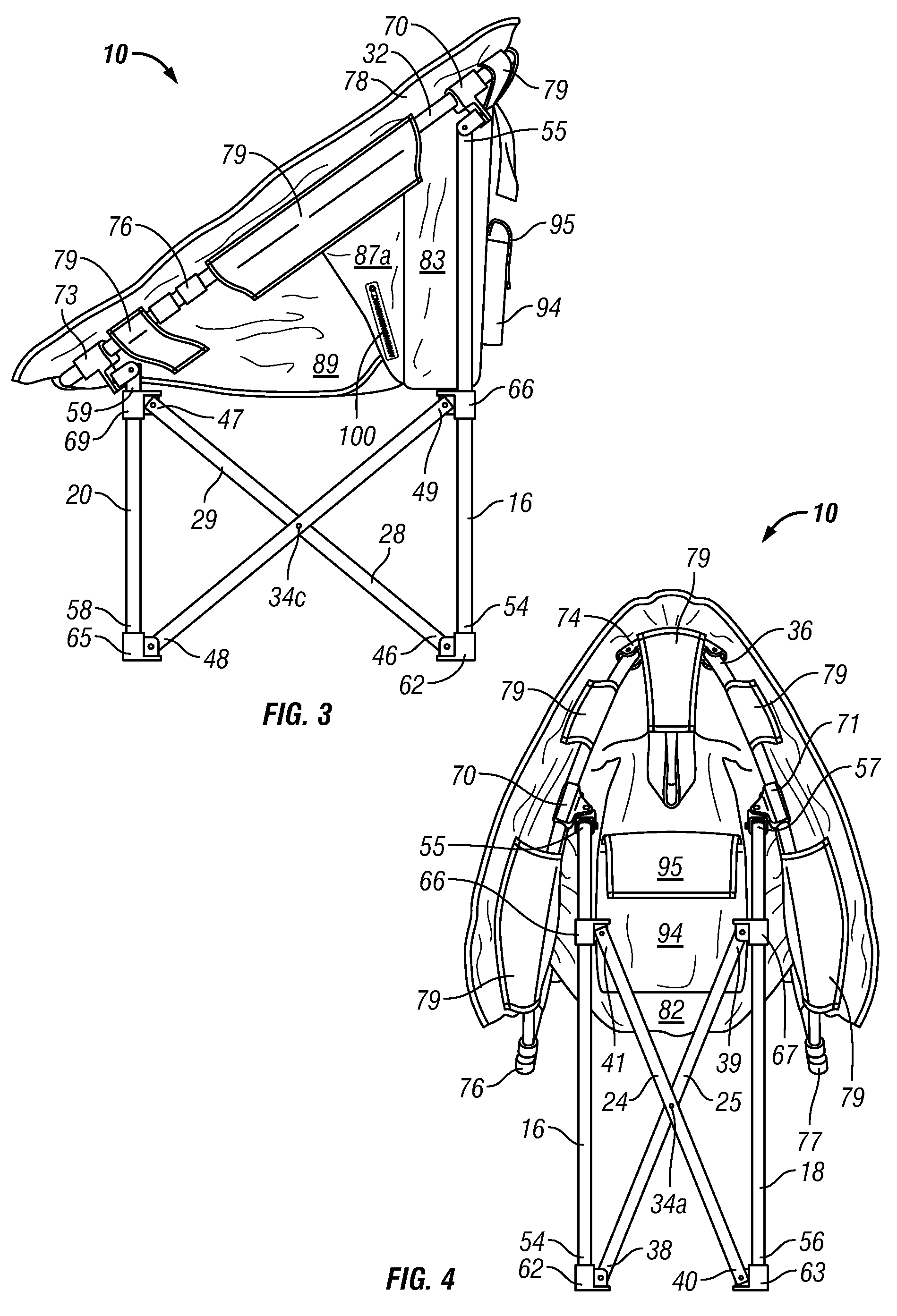
[0034]Referring now in detail to the drawings, wherein like reference characters designate like or corresponding parts throughout the several views, a foldable chair that includes a forced air cooling system with a re-chargeable power source that is enclosed within a housing is illustrated in FIGS. 1 through 8 in accordance with the principles of the present invention.

[0035]As best shown in FIGS. 1-3, the foldable chair 10 is defined by a chair assembly 12 and a forced air cooling system assembly 14. Particularly, the...


PUM


Abstract

A foldable chair, which includes a forced air cooling system. The foldable chair includes a frame member. A flexible seat, which includes a meshed back rest suspends from the frame member. A fan bag, which has a pocket, is attached to the meshed back rest of the flexible seat. A fan is located at the bottom of the fan bag and is electrically disconnectable to a re-chargeable power source that is housed in a housing, which has an ON / OFF toggle switch so as to supply power to the fan.

Description

BACKGROUND OF THE INVENTION[0001]1. Field of the Invention[0002]This invention relates generally to a foldable chair, and more particularly, the present invention relates to a readily foldable chair having a forced air cooling system.[0003]2. Description of the Prior Art[0004]As an alternative to being indoors, people all over the world have enjoyed spending their free time at outdoor events. Particularly in America, football has been an extremely popular outdoor sport to attend. In fact, many people no longer just attend the football game itself, but also arrive early to the surrounding parking lots of the stadiums to participate in, what has become known as, tailgating.[0005]Tailgating typically involves grilling food, consuming beverages and socializing while standing around the back, or tail, of the parked cars in the parking lot until the football game begins. The popularity of tailgating in the past few decades has started to attract many families to the parking lots of colleg...

Claims


Application Information

Patent Timeline
01 Jul 2010
Publication
US20100164256A1
IPC
A47C7/74; A47C4/28
CPC
A47C4/286; A47C7/744
Inventors
SALISBURY, KEITH B.