

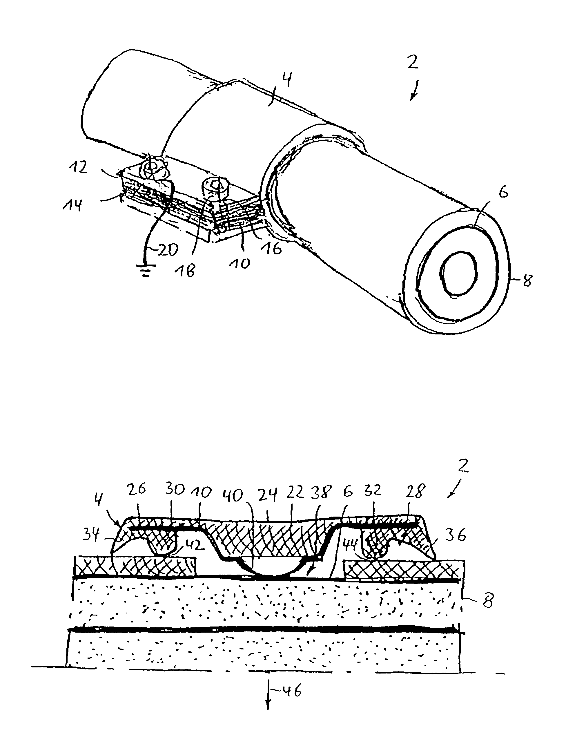
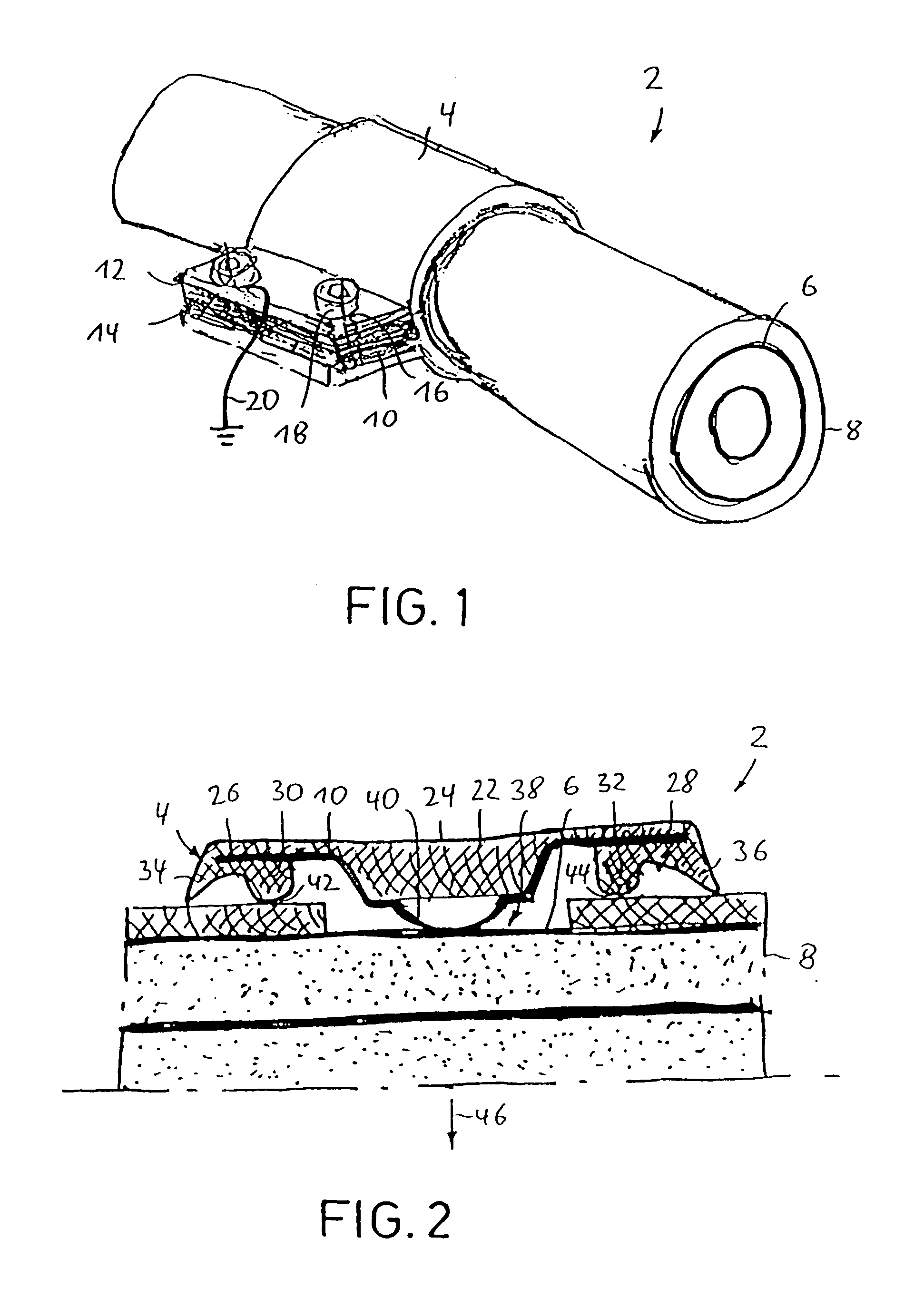
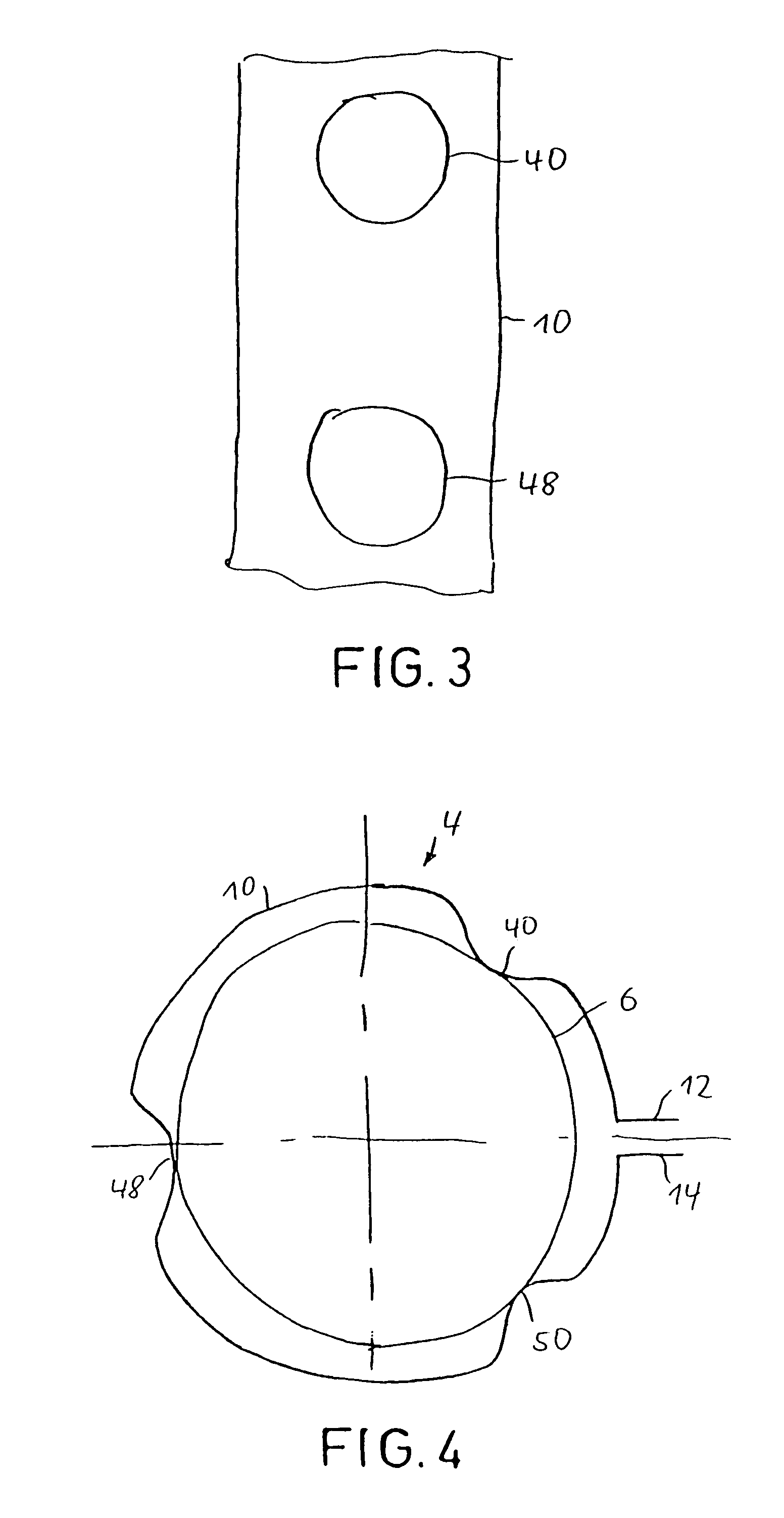
Device for contacting in particular elongated, illustratively substantially cylindrical bodies such as cables or pipes/tubes
a technology of substantially cylindrical bodies and devices, which is applied in the direction of electrically conductive connections, coupling device connections, flexible pipes, etc., can solve the problems of adapter slippage, not being affixed in the desired position to the base structure, and laborious and costly, and achieves simple and economical manufacture and installation.
- Summary
- Abstract
- Description
- Claims
- Application Information
AI Technical Summary
Benefits of technology
Problems solved by technology
Method used
Image

Examples
second embodiment
[0069]FIG. 5 illustrates an elevation of the radial inside surface of the device 2 of the invention whereby the contact protrusions consist of blades 52 and 54 stamped out of contact element 10.
[0070]FIG. 6 illustrates a radial section of the device of the invention shown in FIG. 5 and showing another blade 56 so that each of blades 52, 54 and 56 are equidistant from each other in a circumferential direction of the base structure 4 and are bent toward the side of the base structure 4 facing the outer conductor 6 to be contacted when in an assembled position to project such that they rest resiliently against outer conductor 6.
third embodiment
[0071]FIG. 7 illustrates an axial section of the device of the invention 2 whereby the protrusion of contact element 10 forming the contact consists of a bead 52 running in a circumferential direction of the base structure 4 substantially over the entire length of the base structure 4 in that direction. The elastic part 22 closely rests against the contact element 10 in the zone of the bead 58.
[0072]FIG. 8 illustrates a schematic elevation view showing the radial inside surface of the device 2 shown in FIG. 7.
fourth embodiment
[0073]FIG. 9 illustrates an axial section of the present invention whereby elastic part 22 is mounted a distance away from the contact element 10 in the zone of the bead 58.
[0074]FIG. 10 illustrates a radial section of the device shown in FIG. 9.
PUM
 Abstract
Description
Claims
Application Information