High Frequency Module for Filling Level Measurements in the W-Band

Active Publication Date: 2010-04-29
VEGA GRIESHABER GMBH & CO
View PDF29 Cites 22 Cited by
  • Summary
  • Abstract
  • Description
  • Claims
  • Application Information

AI Technical Summary

Benefits of technology

[0011]In order to bond the housing onto the printed circuit board, for example conductive silicon is used. There is no need to carry out roll seam welding or laser welding in order to seal the housing, because it is not mandatory for the housing to be airtight. There is no need to fill the housing with inert gas. Consequently the high-frequency module can be made economically, simply and at reduced effort.
[0012]According to a further exemplary embodiment of the invention,

Problems solved by technology

The reason for this is that in the case of the high frequencies in the W-band the parasitic effects of a component housing may very consid

Method used


Image

  • High Frequency Module for Filling Level Measurements in the W-Band
  • High Frequency Module for Filling Level Measurements in the W-Band
  • High Frequency Module for Filling Level Measurements in the W-Band

Examples


Example

[0042]The illustrations in the figures are diagrammatic and not to scale.

DETAILED DESCRIPTION

[0043]In the following description of the figures the same reference characters are used for identical or similar elements.

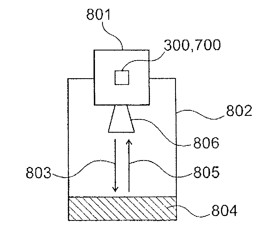
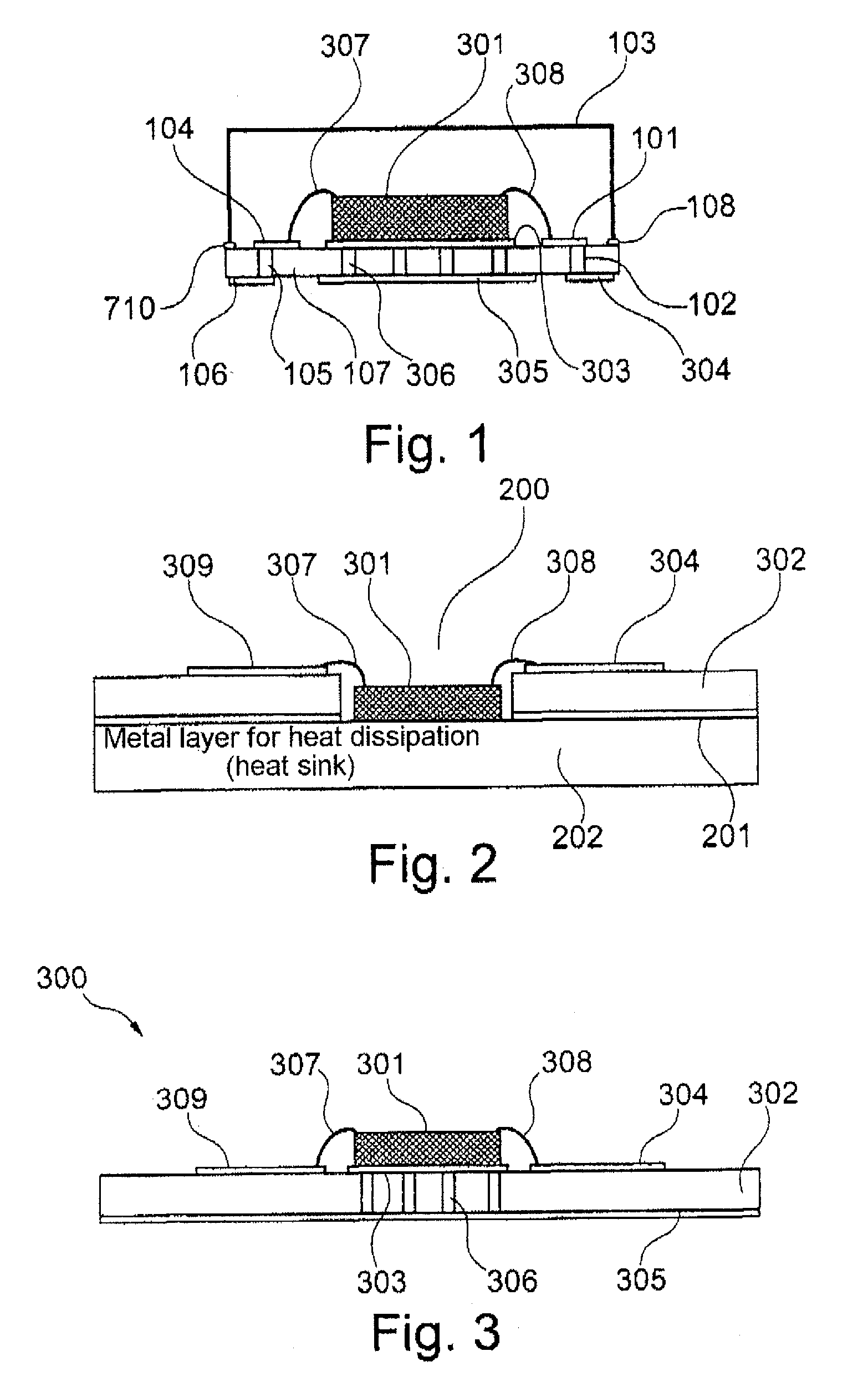
[0044]FIG. 1 shows a cross-sectional view of a high-frequency module that comprises a microwave semiconductor (chip) 301 which has been placed on a base board 107 (for example made of ceramic material). Between the base board 107 and the chip 301 there is a metal layer 303.

[0045]The chip 301 is connected to the ongoing signal lines 104 or 101 by way of the bond wires 307, 308. By way of corresponding through-hole platings 102, 105 the signal lines 101, 104 are led through the base board 107 and then continue on the underside of the base board (see reference characters 304, 106).

[0046]Furthermore, through-hole platings 306 are provided underneath the chip 301, which through-hole platings 306 are connected to the metallic mass connection 305 on the underside of the base bo...


PUM


Abstract

A high-frequency module is for fill level measuring and for use at frequencies of more than 75 GHz. The high-frequency module comprises a microwave semiconductor, a printed circuit board and a housing bonded to the printed circuit board. In order to reduce the power required, operation of the microwave semiconductor takes place in a pulsed manner.

Description

REFERENCE TO RELATED APPLICATIONS[0001]This application claims the benefit of the filing date of EP Application Serial No. 08 167 856.7 filed on Oct. 29, 2008 and U.S. Provisional Patent Application Ser. No. 61 / 109,319 filed on Oct. 29, 2008, the disclosure of which applications is hereby incorporated herein by reference.FIELD OF THE INVENTION[0002]The present invention relates to fill level measuring. In particular, the invention relates to a high-frequency module for fill level measuring at frequencies of more than 75 GHz, to a fill level radar with a high-frequency module, and to a method for operating a fill level sensor with a high-frequency module.TECHNOLOGICAL BACKGROUND[0003]The use of high frequencies in fill level measuring provides many advantages. For example, in this way the components of sensors may be kept smaller.[0004]In fill level measuring in the high-frequency range there are three different frequency bands. Firstly the so-called C-band, which ranges from 4 to 8 ...

Claims


Application Information

Patent Timeline
IPC IPC(8): G01S13/08G01F23/00
CPCG01F23/284G01S7/032H01L2924/12041H01L2924/01019H01L24/48G01S13/88H01L23/055H01L23/552H01L23/66H01L2224/48091H01L2224/48227H01L2924/0102H01L2924/01078H01L2924/1423H01L2924/15153H01L2924/1517H01L2924/16195H01L2924/3025H01L2924/00014H01L2924/00H01L2924/14H01L2924/181H01L2224/45099H01L2224/45015H01L2924/207H01L2924/00012
Inventor SCHULTHEISS, DANIELFISCHER, MICHAEL
Owner VEGA GRIESHABER GMBH & CO
Why Eureka
Try Eureka