[0008]In many practical embodiments, digitized versions or replicas of the smooth functions may be used instead of analog ones while retaining most of the advantages of the invention. The small interference effects caused by
digitization can either be ignored, or accounted for and corrected as required by the application. The modulation functions of two dispersed radiation filters for two different channels are considered to be substantially orthogonal to each other when it is possible to differentiate the contribution to the
detector signal caused by the wavelength component in one of the two channels from that caused by the wavelength component in the other channel without having to solve a simultaneous
system of equations. The definition also allows for a finite number of corrections to compensate for the effects of
digitization. As explained below, for different applications, this definition may be applied differently. In this manner, the time and effort required to decode the amplitude coefficients is greatly reduced. Furthermore, the modulators can be made with filters specifically adapted for certain analytical functions. If modulators with different characteristics are called for to perform a different analytical function, it is a simple matter to replace the modulator by one with the desired properties without altering the
system apparatus. Another
advantage of the invention lies in that the filters of a modulator are at fixed
spatial relationship to each other, so that
wavelength calibration is reduced in determining the alignment of the dispersed image onto the
radius of the disc.
[0009]One embodiment of the
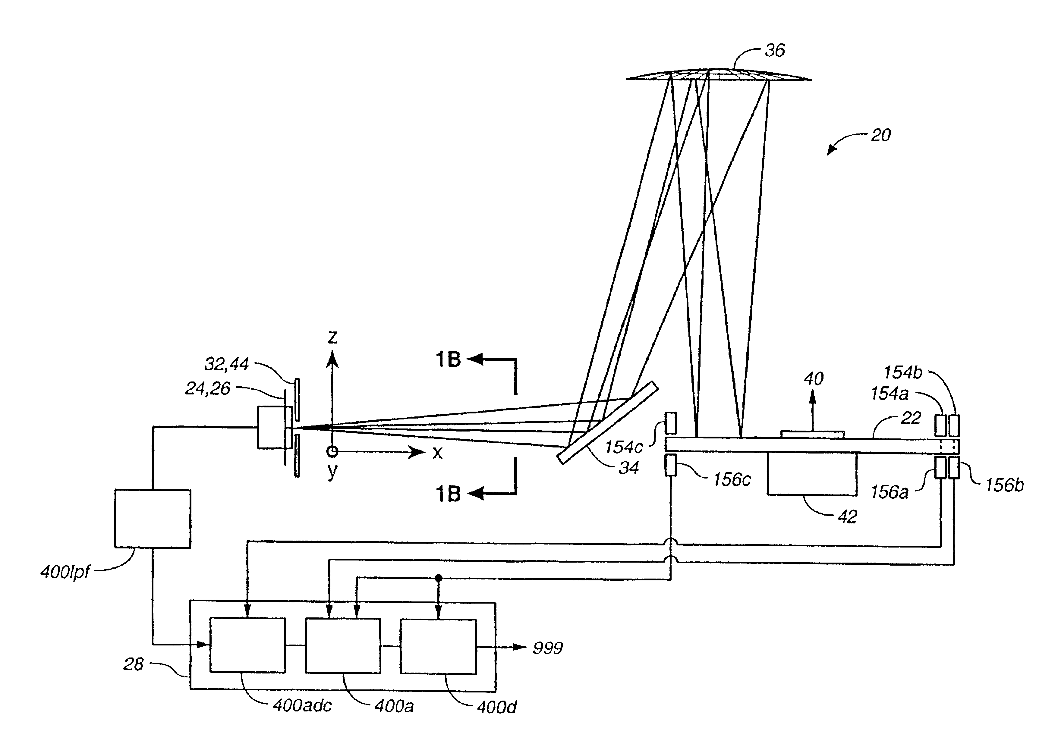
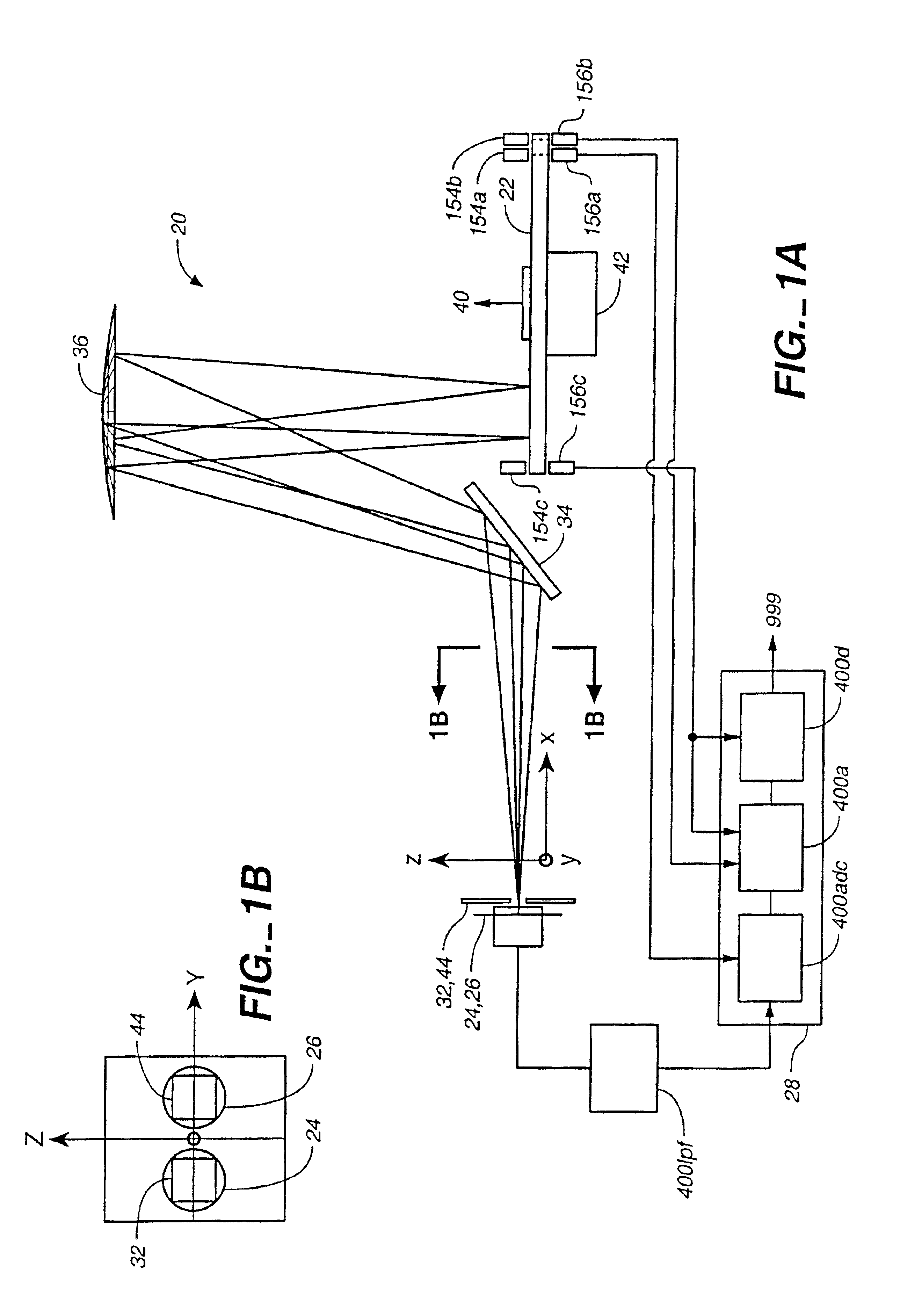
spectrum analyzer of this invention according to one aspect of the invention comprises a source providing radiation, where the radiation includes a plurality of selected wavelength components.
Radiation from the source is collected, dispersed and focused to form an image dispersed by wavelength onto a plane. A two-dimensional spatial modulator positioned in the plane modulates amplitudes of the wavelength components to
encode each component, such that the amplitude of each encoded component has three or more distinct levels of contrast as a function of time. The encoded beam is collected and directed towards a
detector and signals generated by the
detector are sampled and analyzed. Preferably, at least two of the modulation functions for encoding two corresponding wavelength components have the optimum 50%
duty cycle and are substantially orthogonal, so that the amplitudes of the two encoded components present in the total detector signal may be distinguished from each other without solving a
system of
simultaneous equations. Preferably, the modulator is rotated about an axis or otherwise reciprocated in a direction, where the modulator modulates the wavelength components so that the amplitude of each encoded component has three or more distinct levels of contrast as a function of time. More preferably, at least two of the modulation functions of the modulator have the optimum 50%
duty cycle and are substantially orthogonal along an azimuthal axis relative to the rotation.
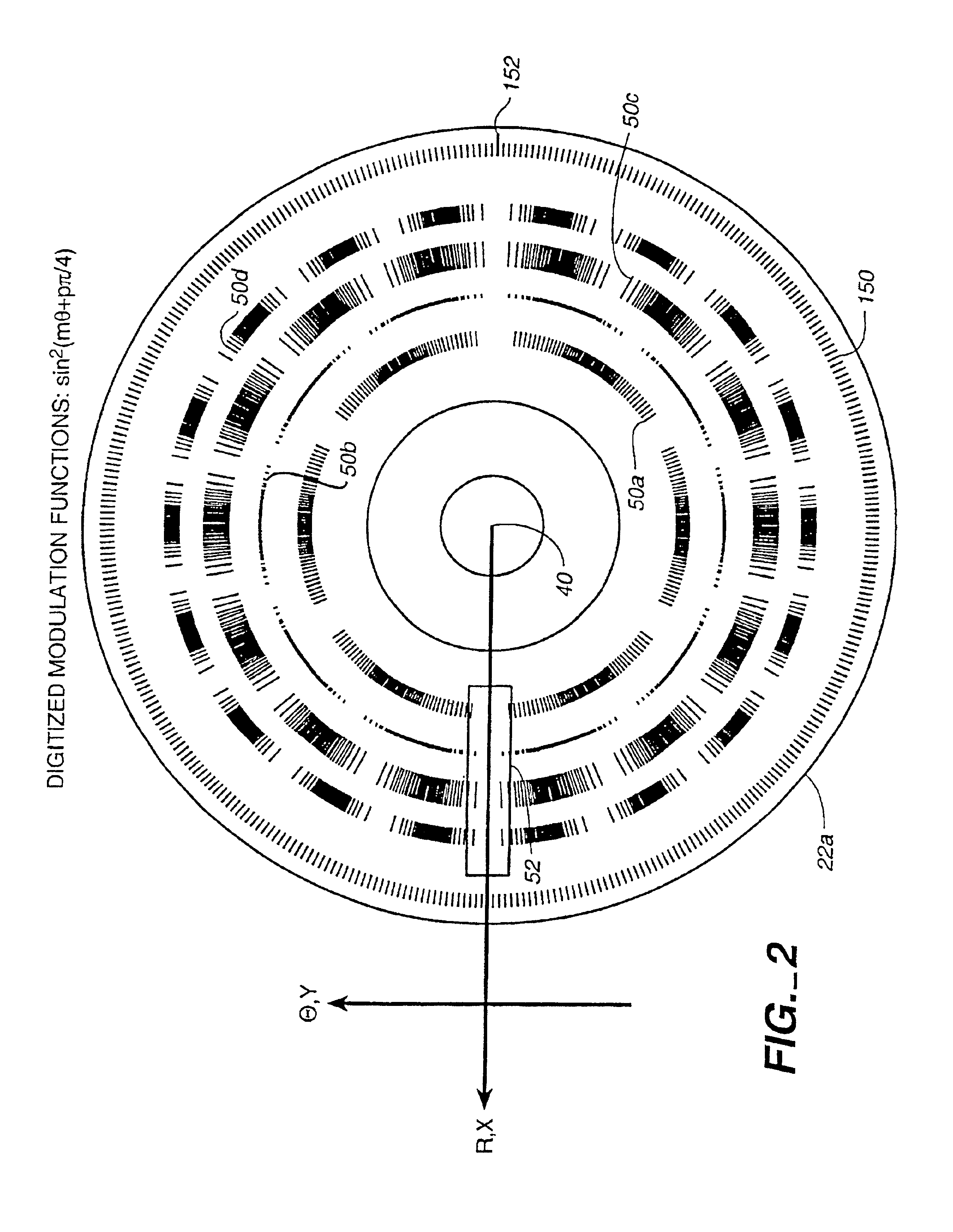
[0010]Another aspect of the invention and useful for the above-described
spectrum analyzer is a two-dimensional spatial radiation modulator adapted to be rotated about an axis. The modulator has a plurality of radiation filters at different radii from the axis for modulating amplitudes of different wavelength components of an incident
radiation beam to
encode the beam, so that the amplitude of each encoded component is a function of a rotation angle of the modulator about the axis. Preferably, one or more of the filters has a
modulation function that encodes the amplitude of the corresponding component so that the encoded component has three or more distinct levels of contrast over time when the modulator is rotated about the axis. More preferably, the modulation functions are smooth functions or digitized replicas thereof, obtained by
rounding up or
rounding down to a finite number of levels of contrast, and the modulation functions of two filters for modulating two different wavelength components have the optimum 50% duty cycle and are substantially orthogonal. In the preferred embodiment, the modulator contains a series of timing marks and the analyzer has a number of optical switches which are triggered by the timing marks to establish the absolute
angle of rotation for decoding purposes. Most preferably, the timing marks will also trigger the
data acquisition from the detector and the decoding
algorithm, which in turn, will substantially relax the requirements on the stability of the modulators rotational period. Preferably, the analyzer will have a dedicated radiation source and an analog detector which is partially interrupted by the timing marks to detect platter wobble or a misaligned pattern on the modulator. More preferably, the signal generated by the analog detector would be used as input by the decoding
algorithm or the analytical function to compensate for the undesired effects of platter wobble or a misaligned pattern. Most preferably, the signal generated by the analog detector would be used as input to control the position of one or more optical elements to keep the diffracted image centered on the modulator pattern. Preferably, the analyzers
operating system will include an
algorithm which will detect transients in the signal levels of the wavelength components which occur during a rotational period of the modulator. Most preferably, the algorithm will include a feedback mechanism to increase the
motor speed in response to the detection of sub-rotational-period signal transients and decrease the
motor speed in response to extended periods of time where the signal is stable.
[0011]Another two-dimensional spatial radiation modulator that will be useful for
spectral analysis includes a two-dimensional spatial radiation modulator adapted to be rotated about an axis, or otherwise reciprocated in a direction. The modulator includes at least one pair of radiation filters which are
out of phase such that the signal resulting from the filter pair can be nulled by balancing the intensity of the light which is incident on the two filters. In that manner, the difference in the
light intensity incident on the two filters can be measured directly, rather than inferring the difference by subtraction, an inefficient approach which wastes
dynamic range of the
analog to digital converter (ADC) in the event that such a converter is used. Preferably, one or more of the filter pairs has a
modulation function that encodes the amplitude of the corresponding component difference so that the encoded component difference has three or more distinct levels of contrast over time when the modulator is rotated about the axis. More preferably, the modulation functions are smooth functions or digitized replicas thereof, obtained by
rounding up or rounding down to a finite number of levels of contrast, such that the modulation functions of two filter pairs for modulating two different wavelength component differences have the optimum 50% duty cycle and are substantially orthogonal.
[0012]Another two-dimensional spatial radiation modulator that will be useful for
spectral analysis includes a two-dimensional spatial radiation modulator adapted to be rotated about an axis, or otherwise reciprocated in a direction. The modulator has at least one dispersed radiation filter being in the shape of a band surrounding the axis, where the
radial position of the band is modulated between two different radii from the axis, such that the center wavelength of the reflected radiation is modulated between two different wavelengths when the modulator is rotated about the axis. Preferably the band is serpentine in shape.
[0013]Another two-dimensional spatial radiation modulator useful for spectral analysis is adapted to be rotated about an axis. The modulator has at least one dispersed radiation filter in the shape of a substantially continuous band around the axis, where the band has a width that varies as a function of a rotational angle of the modulator about the axis, to modulate the bandwidth of the reflected radiation.

