

Motor and exhaust method for motor cavity
a technology of exhaust method and motor cavity, which is applied in the direction of electrical apparatus, supports/enclosements/casings, dynamo-electric machines, etc., can solve the problems of limiting the torque of the motor, especially at a low speed, and achieves the effect of lowering the air pressure inside the motor, reducing the torque, and increasing the vacuum
- Summary
- Abstract
- Description
- Claims
- Application Information
AI Technical Summary
Benefits of technology
Problems solved by technology
Method used
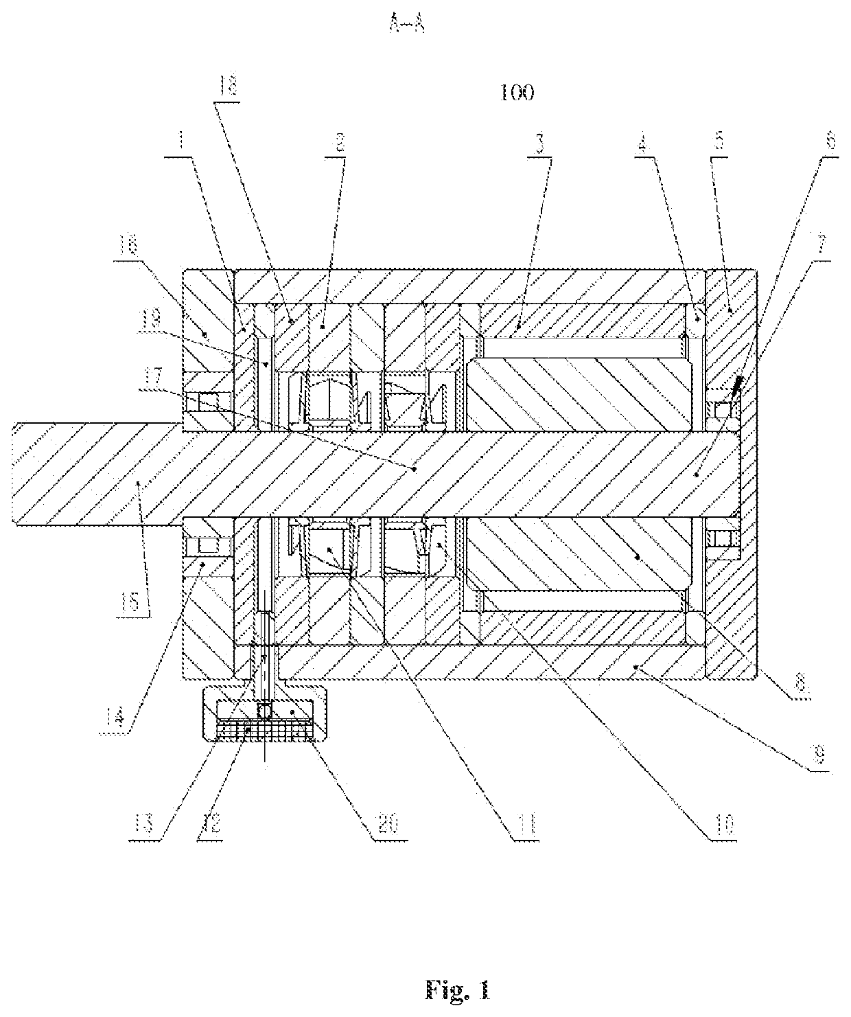
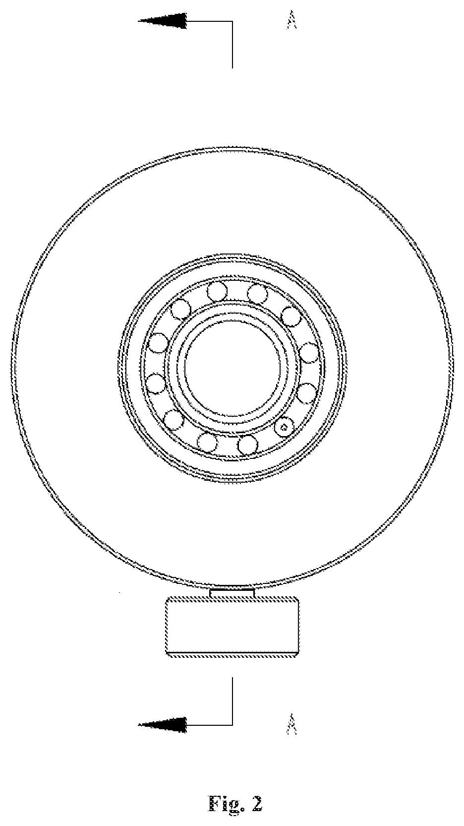
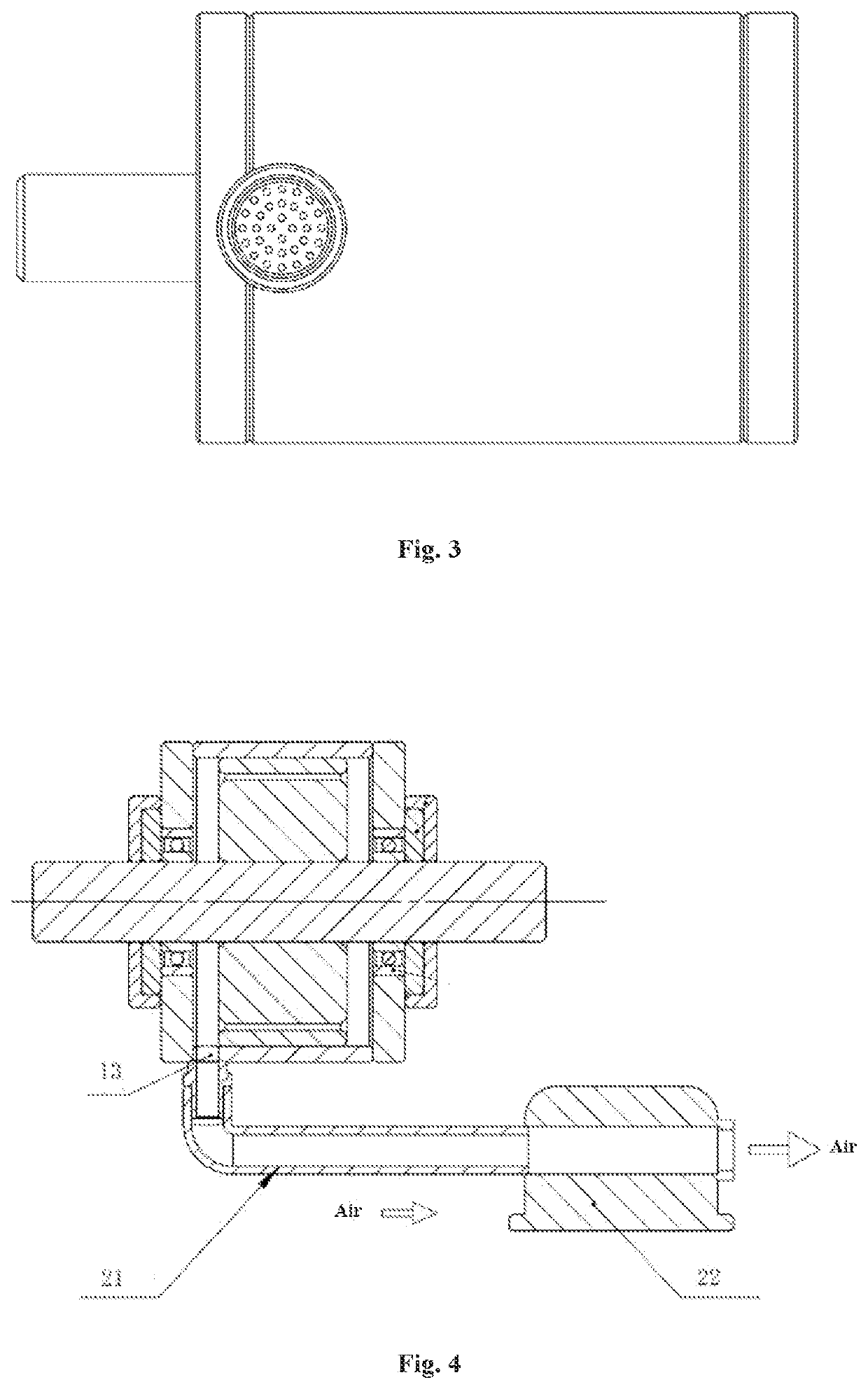
Image

Examples
Embodiment Construction
[0022]Certain exemplary examples will be described below only in a brief manner. Just as those skilled in the art will appreciate, changes in various ways to the examples described herein can be carried out without departing from the spirit or scope of the present invention. Therefore, the drawings and the following description are deemed essentially exemplary, instead of limitative.
[0023]In the specification of the present invention, it need be understood that such terms as “first” and “second” are only used for the purpose of description, rather than indicating or suggesting relative importance or implicitly indicating the number of the designated technical features. Accordingly, features defined with “first” or “second” may, expressly or implicitly, include one or more of such features.
[0024]The disclosure below provides many different embodiments and examples for achieving different structures described herein. In order to simplify the disclosure herein, the following will give ...
PUM
 Abstract
Description
Claims
Application Information