Method and device for controlling an internal combustion engine

A technology of internal combustion engine and combustion method, applied in the direction of internal combustion piston engine, electrical control, engine control, etc., capable of solving problems such as failure of internal combustion engine

Inactive Publication Date: 2016-12-21
ROBERT BOSCH GMBH
View PDF8 Cites 0 Cited by
  • Summary
  • Abstract
  • Description
  • Claims
  • Application Information

AI Technical Summary

Problems solved by technology

However, under unfavorable conditions, for example at an unfavorable crankshaft angle, at least one first attempt to start the internal combustion engine may not be successful

Method used


Image

  • Method and device for controlling an internal combustion engine
  • Method and device for controlling an internal combustion engine

Examples


Embodiment Construction

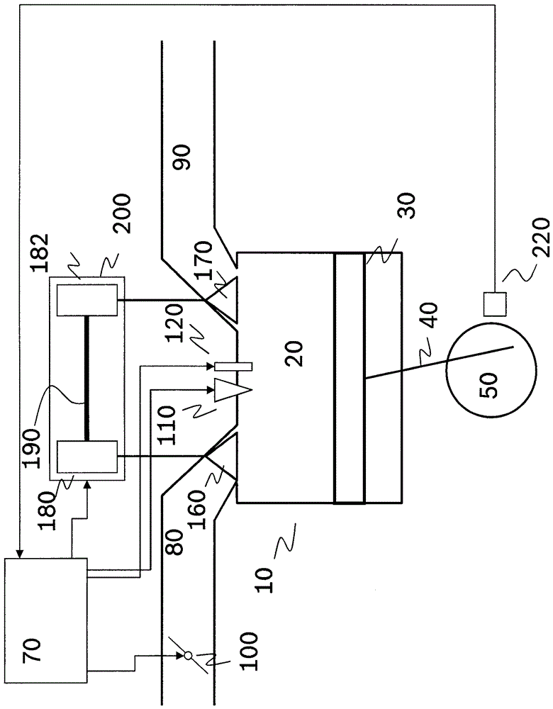
[0017] figure 1 A cylinder 10 of an internal combustion engine is shown, which has a combustion chamber 20 and a piston 30 which is connected to a crankshaft 50 via a connecting rod 40. The piston 30 performs upward and downward movement in a known manner. The reversal point of the movement is called the dead point. The transition from upward motion to downward motion is called top dead center, and the transition from downward motion to upward motion is called bottom dead center. The angular position of the crankshaft 50, the so-called crankshaft angle, is defined with respect to the top dead center in a usual manner. The crankshaft sensor 220 detects the angular position of the crankshaft 50. The crankshaft sensor 220 is formed in such a way that teeth are periodically provided on the gears, that is, at an angular distance of, for example, 6°, the tooth surfaces of which generate signals, and the speed of the crankshaft is determined from the time interval of the signals.

[...


PUM


Abstract

The method involves igniting fuel mixture before passing through a top dead center after detecting the request for stopping the internal combustion engine in a start cylinder (10). The fresh air position units (100,200) for setting fresh air charge in the starting cylinder are provided in fresh air position so that intake fresh air charge sucked in from the cylinder is as large as possible. The starting cylinder located at the starting injection cylinder is turned off and fresh air position units for adjusting the fresh-air charge passing through exhaust stroke. Independent claims are included for the following: (1) internal combustion engine stopping and starting program stored in electrical storage medium; and (2) control and / or regulating device of internal combustion engine.

Description

Technical field [0001] The invention relates to a method and device for controlling an internal combustion engine. Background technique [0002] From DE 19743492 A1, a method for starting an internal combustion engine is known, in which the first injection is carried out during start-up in a cylinder whose piston is in the power phase. As a result, the crankshaft is in forward motion, and the internal combustion engine is started. However, under unfavorable conditions, such as an unfavorable crankshaft angle, at least one first start attempt of the internal combustion engine may be unsuccessful. It is also possible that the internal combustion engine turns first at an unfavorable crankshaft angle, so the gas spring is compressed in the cylinder in the power stroke, thereby causing the rotation direction of the internal combustion engine to reverse, and then it starts in the forward rotation direction. [0003] A device is generally known in the prior art that changes the stroke d...

Claims


Application Information

Patent Timeline
Patent Type & Authority Patents(China)
IPC IPC(8): F02D41/06F02D41/30F02D13/00
CPCF02D41/0005F02D41/042F02D2013/0292F02D2041/001F02D2041/002F02N11/0814F02N19/004F02N99/004F02N99/006Y02T10/40
Inventor E.卡瓦K.赖A.施米特B.希勒U.斯伊伯C.格斯劳尔
Owner ROBERT BOSCH GMBH
Why Eureka
Try Eureka