Hybrid electro-mechanical transmission with single motor/generator and method of control

a technology of electro-mechanical transmission and single motor, applied in the direction of locomotive transmission, electric motor propulsion transmission, gearing, etc., can solve the problems of limited power supply, limited power reception, etc., and achieve the effects of reducing emissions, fuel economy improvement, and reducing costs

Inactive Publication Date: 2007-08-14
GM GLOBAL TECH OPERATIONS LLC
View PDF14 Cites 99 Cited by
  • Summary
  • Abstract
  • Description
  • Claims
  • Application Information

AI Technical Summary

Benefits of technology

[0011]A reduced cost, compact hybrid electro-mechanical transmission having only a single motor / generator is provided. Benefits of an electro-mechanical transmission, such as emissions reductions and fuel economy improvement, may be realized while cost reduction is possible due to the elimination of a second motor / generator. Additionally, the hybrid electro-mechanical transmission herein accomplishes synchronous shifting between continuously variable operating modes. (As used herein, a “mode” is a particular operating state, whether encompassing a continuous range of speed ratios or only a fixed speed ratio, achieved by engagement of a particular torque-transmitting mechanism or torque-transmitting mechanisms.) In other words, the transmission offers synchronous shifting between variable ranges, thus optimizing shift feel and passenger comfort. Synchronous shifting means that torque-transmitting mechanisms used in an off-going speed ratio are released as torque-transmitting mechanisms used in an on-coming speed ratio are engaged, while the relative speeds of the two operative parts of each of the torque-transmitting mechanisms are very low (essentially zero). Because only a single motor / generator is employed, its ability to provide power (when acting as a motor) and to receive power (when acting as a generator) is limited by the energy storage capacity of a battery from which the single motor / generator receives power for powering the transmission or to which the motor / generator delivers power that is received from the transmission. Accordingly, a method described below permits control of the transmission at optimal energy efficiency in light of the limitations of the battery.
[0013]At least two continuously variable operating modes are achieved by the transmission. A first torque-transmitting mechanism is selectively engageable to establish a first continuously variable operating mode that has a first preferred range of speed ratios. A second torque-transmitting mechanism is selectively engageable to establish a continuously variable operating mode that is characterized by a second preferred range of speed ratios. Preferably, the first torque-transmitting mechanism connects the single motor / generator with one of the members of the differential gear set and engagement of the second torque-transmitting mechanism connects the single motor / generator with another member of the differential gear set. The speed of the output member is a combination of the speed of the input member and the speed of the motor / generator. As is well understood by those skilled in the art, in a continuously variable operating mode, power is provided by the engine and also flows from or to the motor / generator. Having more than one continuously variable operating mode reduces the amount of motor / generator power necessary to control the speed ratio through the transmission from input member to output member.

Problems solved by technology

Because only a single motor / generator is employed, its ability to provide power (when acting as a motor) and to receive power (when acting as a generator) is limited by the energy storage capacity of a battery from which the single motor / generator receives power for powering the transmission or to which the motor / generator delivers power that is received from the transmission.

Method used


Image

  • Hybrid electro-mechanical transmission with single motor/generator and method of control
  • Hybrid electro-mechanical transmission with single motor/generator and method of control
  • Hybrid electro-mechanical transmission with single motor/generator and method of control

Examples


Embodiment Construction

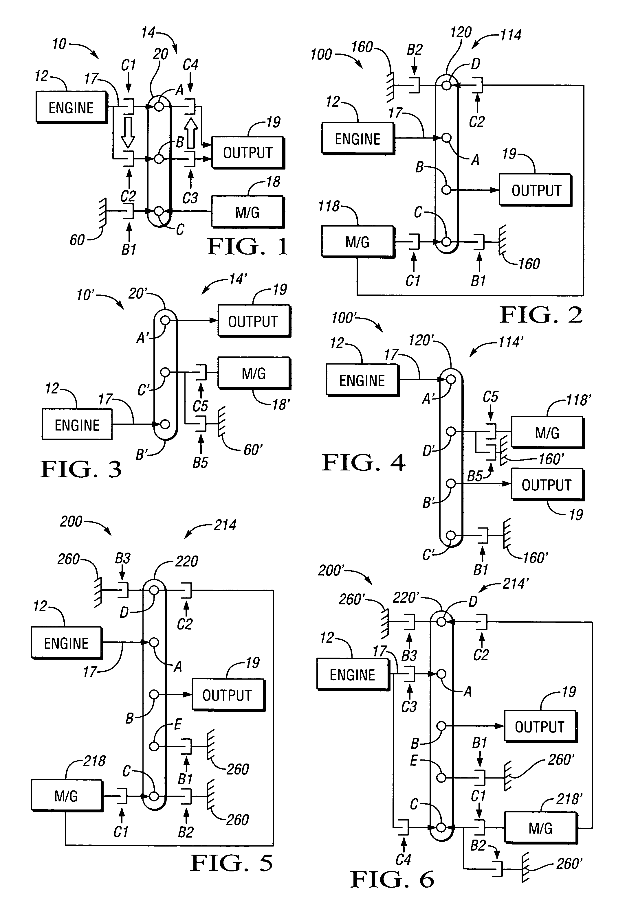
[0034]Referring to the drawings, wherein like reference numbers refer to like components, FIG. 1 shows a powertrain 10 including an engine 12 connected to one embodiment of an electro-mechanical transmission designated generally by the numeral 14. The transmission 14 is designed to receive at least a portion of its driving power from the engine 12. The engine 12 has an output shaft that is connectable to an input member 17 of the transmission 14. The input member 17 is selectively connectable to a gear set member of transmission 14 represented by a first node A of a lever 20 via a first clutch C1. The engine 12 is operatively connected to node A of the lever 20 when C1 is engaged. The lever 20 represents a simple planetary gear set, and may be referred to as such. The lever 20 includes the first node A as well as a second and third node B and C, respectively. The nodes A, B and C represent a first, second and third member of the planetary gear set 20, preferably a ring gear member, ...


PUM


Abstract

An electro-mechanical transmission is provided having only a single motor / generator, at least one differential gear set and two torque-transmitting mechanisms. A first of the torque-transmitting mechanisms is selectively engageable to establish a first continuously variable operating mode and a second of the torque-transmitting mechanisms selectively engageable to establish a second continuously variable operating mode and a synchronous shift between the two operating modes is achievable. A method of control is provided in which vehicle operating characteristics are analyzed to identify a target operating state in terms of operating mode and ratio based on the available motor torque and motor power and on maximizing energy efficiency. The transmission is controlled to approach this operating mode as closely as possible and the diverge away from the optimum torque operating with zero net battery use as the battery charge of the battery connected with the motor / generator accumulates or depletes.

Description

TECHNICAL FIELD[0001]The present invention relates to electrically variable transmissions having a single electric motor / generator and a method of control therefore.BACKGROUND OF THE INVENTION[0002]Internal combustion engines, particularly those of the reciprocating piston type, currently propel most vehicles. Such engines are relatively efficient, compact, lightweight, and inexpensive mechanisms by which to convert highly concentrated energy in the form of fuel into useful mechanical power. A novel transmission system, which can be used with internal combustion engines and which can reduce fuel consumption and emissions, may be of great benefit to the public.[0003]The wide variation in the demands that vehicles typically place on internal combustion engines increases fuel consumption and emissions beyond the ideal case for such engines. Typically, a vehicle is propelled by such an engine, which is started from a cold state by a small electric motor and relatively small electric sto...

Claims


Application Information

Patent Timeline
Patent Type & Authority Patents(United States)
IPC IPC(8): F16H3/72B60L50/10B60K6/365B60K6/387B60K6/40B60K6/48
CPCB60K6/365B60K6/40B60K6/48B60W10/02B60W10/08B60W10/115B60W10/26F16H3/725B60K6/387Y02T10/6221B60W20/00F16H2200/0039F16H2200/0043F16H2200/2005F16H2200/2007F16H2200/2023F16H2200/2041F16H2200/2046B60K2006/4816F16H2200/2025Y02T10/62B60W20/10B60W10/10B60W10/06
Inventor HOLMES, ALAN G.SCHMIDT, MICHAEL R.KLEMEN, DONALD
Owner GM GLOBAL TECH OPERATIONS LLC
Why Eureka
Try Eureka