Tomosynthesis in a limited angular range

Inactive Publication Date: 2004-11-02
KONINKLIJKE PHILIPS ELECTRONICS NV
View PDF8 Cites 97 Cited by
  • Summary
  • Abstract
  • Description
  • Claims
  • Application Information

AI Technical Summary

Problems solved by technology

However, when the angular range is reduced further, contour lines of o

Method used


Image

  • Tomosynthesis in a limited angular range
  • Tomosynthesis in a limited angular range
  • Tomosynthesis in a limited angular range

Examples


Embodiment Construction

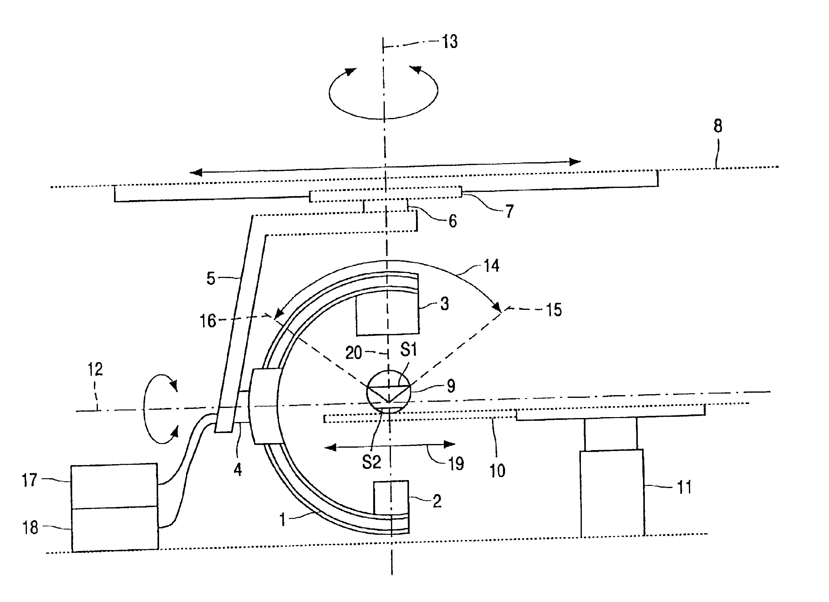
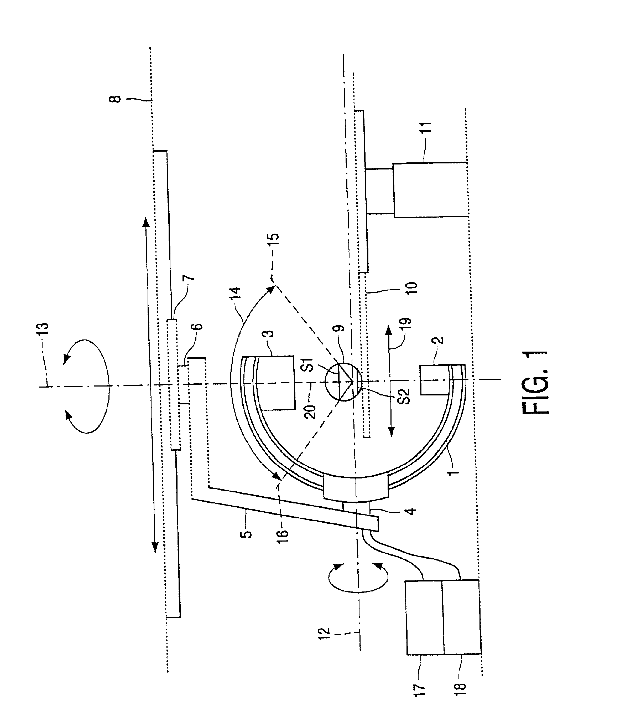
An X-ray device in accordance with the invention as shown in FIG. 1 includes a C-arm 1, the ends of which accommodate an X-ray source 2 and a facing X-ray detector 3. The C-arm 1 is suspended from an L-arm 5, by way of a pivot 4, so as to be rotatable about the horizontal propeller axis 12. The L-arm 5 is suspended from a displaceable carriage 7 by way of a further pivot 6; said carriage is suspended from the ceiling 8. The pivot 6 enables rotation about the vertical axis 13. The L-arm 5 can be displaced in the horizontal direction by way of the carriage 7. An object 9 being examined (symbolically shown), for example a patient, is arranged on a patient table 10; and said patient table is mounted on a base 11 whose height can be adjusted and which is also displaceable in the horizontal direction 19. A control unit 17 controls the X-ray device. Image processing, in particular, the formation of X-ray layer images from the acquired X-ray projection images, is performed by means of an im...


PUM


Abstract

A method and system of forming an X-ray layer image of an object being examined by an X-ray device having an X-ray source and an X-ray detector is described. At least one of the X-ray source and the X-ray detector can be displaced in an angular range around the object in order that X-ray projection images are acquired from different directions. When forming only a single X-ray layer image, or a plurality of X-ray layer images of parallel layers of the object, the time required for the acquisition of the X-ray projection images is notably reduced by forming the X-ray layer image directly from the X-ray projection images, where the resulting X-ray layer image is situated in a plane which extends essentially perpendicularly to the bisector of the angular range of displacement. The angular range of displacement can be less then 180°. The system and method is notably applicable to a C-arm X-ray device, in which the angular range can be chosen at will.

Description

1. Field of the InventionThe invention relates to a method of forming an X-ray layer image of an object, and to an X-ray device for carrying out such a method.2. Description of the Related ArtThe formation of X-ray layer images of an object by utilizing tomosynthesis has been known for a long time. In tomosynthesis, the X-ray source and the X-ray detector are displaced in opposite directions in planes extending parallel to the object being examined and parallel to one another; and then X-ray projection images of the object being examined are acquired from different positions. Using suitable reconstruction methods, layer images of layers of the object being examined can be formed from such X-ray projection images, where said layer images extend parallel to the planes in which the X-ray source and the X-ray detector were moved.It is also known to move the X-ray source and the X-ray detector along circular trajectories around the object being examined, for example, by means of a C-arm....

Claims


Application Information

Patent Timeline
IPC IPC(8): A61B6/00A61B6/03G06T11/00
CPCA61B6/025A61B6/4464A61B6/4441
Inventor KOPPE, REINERKLOTZ, ERHARD PAUL ARTHUROP DE BEEK, JOHANNES CATHARINA ANTONIUS
Owner KONINKLIJKE PHILIPS ELECTRONICS NV
Why Eureka
Try Eureka