
Magnetic clasp device for clothing accessories

Active Publication Date: 2012-08-30
MANUELLO GERARLD
View PDF16 Cites 86 Cited by
  • Summary
  • Abstract
  • Description
  • Claims
  • Application Information

AI Technical Summary

Benefits of technology

[0021]One aim of the present invention is to propose a magnetic clasp device implementing a magnetic clasp for a clothing accessory that is simple and fast, while simultaneously offering several possibilities for adjusting the size of the clothing accessory.
[0022]It is also desirable to offer magnetic clasp devices in which the outside magnetization is minor or nonexistent, such that it cannot interact or interfere with any electronic device and in no way bothers the user during wear.

Problems solved by technology

Regarding belts, and in particular buckle belts, it has been observed that fastening a buckle belt is not always very easy when the leather of the belt is too stiff or the holes for adjusting the size of the belt are not well pierced.
In fact, in the context of a traditional buckle belt, with a metal buckle prong, spur or tab, it is difficult to insert said spur or prong into said holes making it possible to adjust the size when the latter are poorly formed.
Furthermore, with time, the most used hole tends to widen, become damaged and deteriorate.
However, these are sometimes necessarily missing, for example when the belt is worn on a dress or sweater.
Positioning a carrier at the proper distance to immobilize the ends of the belts regardless of the adjustment of the size by the user is complex.
In the case of belts or similar devices having integrated stationary carriers, they are not adapted to the size of all people, and if they are movable, over time the leather tends to move and the carrier only maintains the piece of leather at the free end of the belt for a limited period of time.
However, these magnetic buckle belts are not fully satisfactory.
In fact, on the one hand, the magnetic buckle system is often complex to use and, on the other hand, it only has a single fastening point between the two ends of the belt, which causes risks of having the magnets of the system put in place to close the belt jump fairly frequently.
Furthermore, if it is provided to maintain these magnets using a system preventing them from jumping, the removal and opening of the belt then also becomes complicated.
Furthermore, there are many drawbacks that result from using a magnetic clasp on a clothing accessory such as a belt.
It is also possible to observe an upset in the operation of active electronic implants, such as pacemakers or defibrillators, and implants that can be activated by applying a magnetic, thereby putting the wearers of the accessory in danger.
Furthermore, most often, the magnets of the metal clasps are also too large and unattractive or too small and ineffective.
Furthermore, whatever the clothing accessory with a magnetic or non-magnetic buckle, the clasp is often very thick and causes awkward shapes that make the figure heavier.
Furthermore, the known magnetic clasp devices do not guarantee quick and simple closing of the clothing accessory.
In fact, insertion difficulties due to poor centering of the component pieces of the device have also been observed in accessories provided with magnetic clasp devices.

Method used


Image

  • Magnetic clasp device for clothing accessories
  • Magnetic clasp device for clothing accessories
  • Magnetic clasp device for clothing accessories

Examples


first embodiment

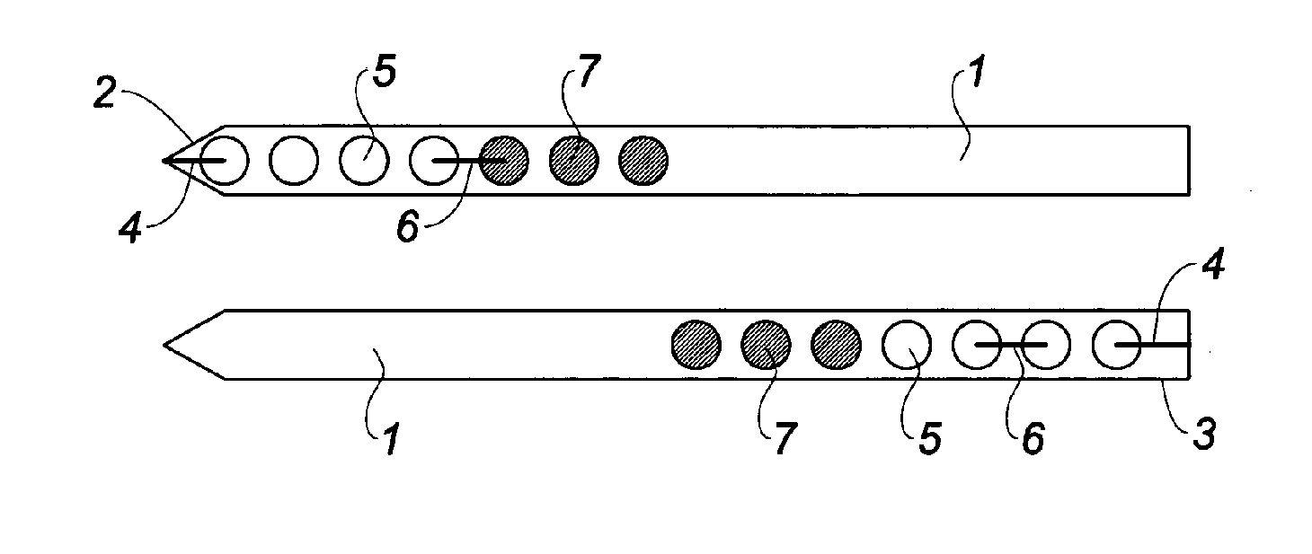
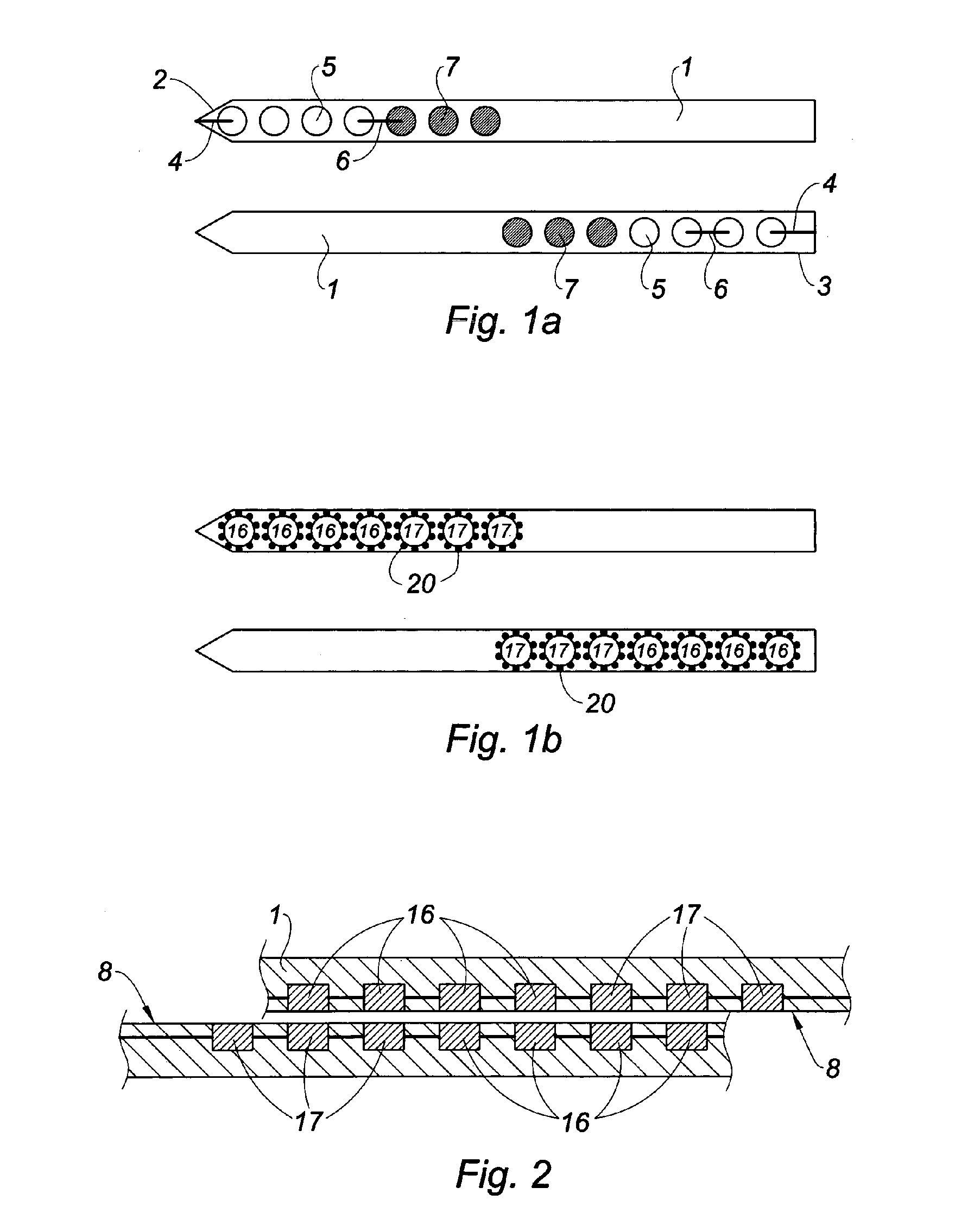
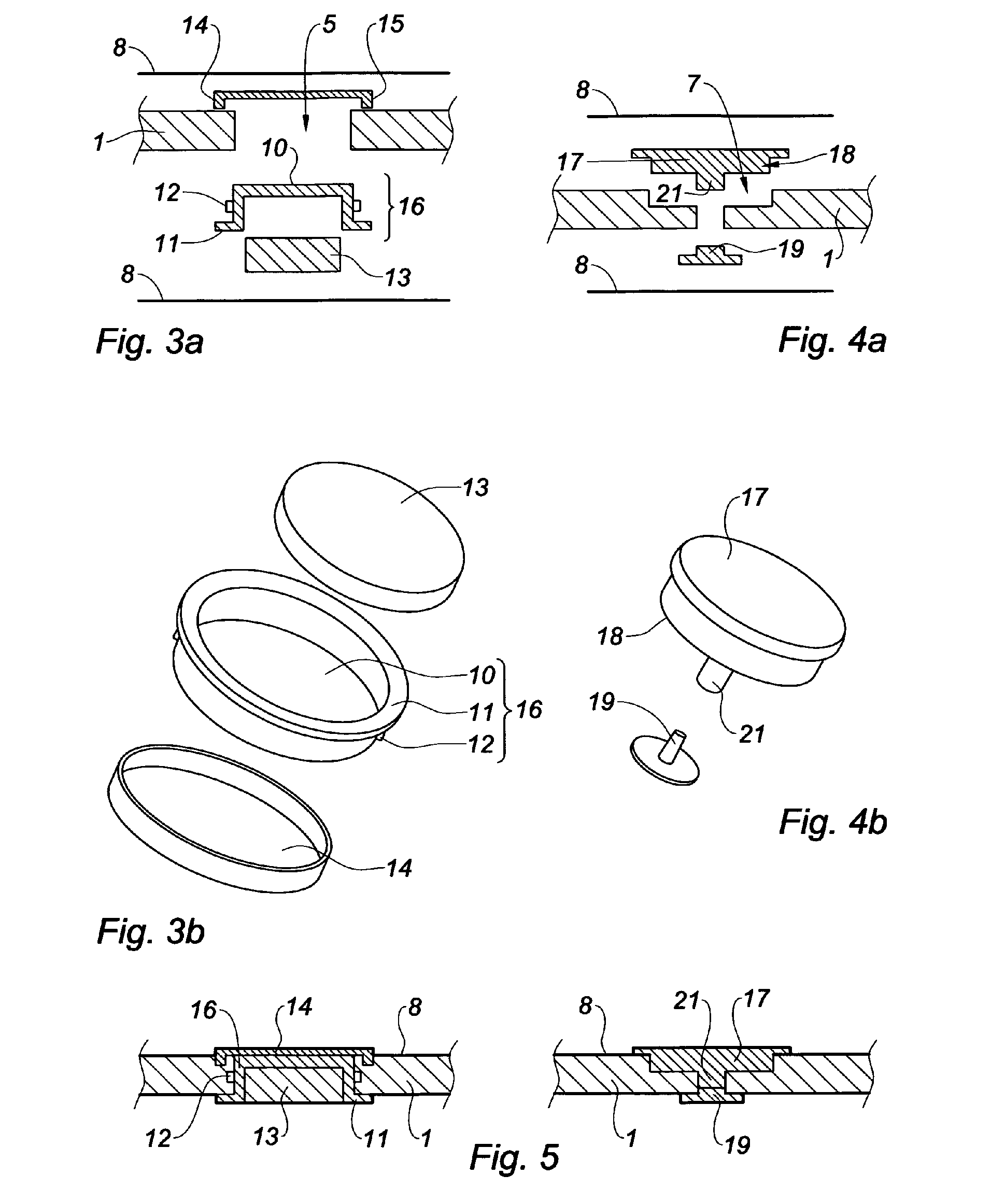
[0155]In reference to FIGS. 1a, 1b and 2, a magnetic clasp device is shown covered with finishing leather 8 that may include permanently magnetized assemblies and ferromagnetic elements hidden under the leather 8 as illustrated in FIGS. 3 to 5 in a first alternative embodiment.

[0156]As illustrated in FIGS. 3a and / or 3b and 5, each receptacle 16 intended to receive a permanent magnet 13 is fastened in one of the holes 5 made beforehand in the inner leather of the belt 1 not yet covered with finishing leather 8 following a specific arrangement as previously described relative to FIGS. 1a, 1b and 2, in particular on the portion called upon to close on the other, starting from the end 2 of the belt 1 and leaving a small margin 4.

[0157]Said hole 5 can pass all the way through the leather of the belt 1 through the thickness of said receptacles 16.

[0158]Preferably, each receptacle 16 is glued in the corresponding hole.

[0159]Each hole 5 has a diameter and a depth equal to those of the corre...

second embodiment

[0188]FIGS. 8 to 10 show a magnetic clasp device in which the receptacles 16 provided with magnets 13 and the ferromagnetic elements 17 are visible.

[0189]Holes 5, 7 are made while respecting the same arrangement in the leather 1 as those of the embodiments of FIGS. 1a and 1b.

[0190]The arrangement in the holes 5, 7 of the belt can also be identical to that of the embodiments of FIGS. 1a and 1b with or without a similar number of magnets 13 and ferromagnetic elements 17.

[0191]In a first alternative embodiment of the receptacle according to this embodiment illustrated in FIGS. 9a and 9b, the receptacle 16 is identical to that of FIG. 3a with the exception of the following differences.

[0192]The receptacles 16 in the form of cylinders open at one end and including the bottom 10 are machined with open side edges and the hole 22 passing through the bottom 10 thereof, like the magnets 13 that are housed therein whereof the hole is designated by reference 23.

[0193]In one non-limiting exampl...

third embodiment

[0221]In a third embodiment, the magnetic clasp device includes receptacles 16 provided with visible magnets 13 and ferromagnetic pieces 17 hidden under the finishing leather 8.

[0222]In such an embodiment, through or blind holes are made adapted to allow the placement of the ferromagnetic pieces 17 under the finishing leather 8, these pieces 17 then being inserted or fastened in the holes and the assembly being covered with a finishing material.

[0223]These ferromagnetic pieces 17 preferably have a maximum height equals about of the material in which they are inserted.

[0224]They may either be fastened by simply covering with finishing leather 8, or by a dedicated fastening system.

[0225]It is also possible to produce holes in the finishing material before covering, said holes being intended for the bottom 10 of the receptacles 16 provided with magnets 13 and leading to savings in terms of thickness.

[0226]In this embodiment, the fasteners can also be visible. They may then serve to aff...


PUM


Abstract

The invention relates to a device for magnetic clasping at a plurality of points for a clothing accessory such as a belt, characterised in that said device includes at least one permanently magnetised assembly (13) arranged at one end of one surface of the accessory, while a plurality of ferromagnetic elements (17) and / or permanently magnetised assemblies (13) are arranged longitudinally on the other surface of the accessory at the opposite end thereof (3), the permanently magnetised assemblies of one surface being suitable for attracting a permanently magnetised assembly of the other surface, the permanently magnetised assemblies (13) and / or ferromagnetic elements (17) of each surface being arranged such that, by placing the ends of the two surfaces of the clothing accessory vertically adjacent to one another, a plurality of adjustment positions of the two surfaces are obtained relative to the position of the permanently magnetised assemblies (13) and ferromagnetic elements (17), representing a plurality of possible tightness levels, each permanently magnetised assembly of one surface engaging with a permanently magnetised assembly or a ferromagnetic element of the other surface in each one of the adjustment positions, in order to close any magnetic field.

Description

TECHNICAL FIELD[0001]The present invention relates to a magnetic clasp device for clothing accessories, for example for belts.BRIEF DISCUSSION OF RELATED ART[0002]Regarding belts, and in particular buckle belts, it has been observed that fastening a buckle belt is not always very easy when the leather of the belt is too stiff or the holes for adjusting the size of the belt are not well pierced.[0003]In fact, in the context of a traditional buckle belt, with a metal buckle prong, spur or tab, it is difficult to insert said spur or prong into said holes making it possible to adjust the size when the latter are poorly formed.[0004]Furthermore, with time, the most used hole tends to widen, become damaged and deteriorate.[0005]One or more carriers are also necessary and essential to immobilize the end(s) of the belt, depending on the nature of the buckle, once it is closed.[0006]However, these are sometimes necessarily missing, for example when the belt is worn on a dress or sweater.[000...

Claims


Application Information

Patent Timeline
IPC IPC(8): H01F7/02A44B11/25
CPCA41F1/002A41F9/002Y10T24/32A45C13/1069A44D2203/00
Inventor MANUELLO, GERARLD
Owner MANUELLO GERARLD
Learn More