
Method and device for sending uplink burst data in passive optical network system

Active Publication Date: 2011-04-28
HUAWEI TECH CO LTD
View PDF8 Cites 6 Cited by
  • Summary
  • Abstract
  • Description
  • Claims
  • Application Information

AI Technical Summary

Benefits of technology

[0008]Various embodiments of the present invention provide a method for providing uplink burst data in a PON system in which spectrum component of a synchronization pattern are relatively uniformly distributed throughout the spectrum interval to thereby allow the use of a relatively simple equalizer at the reception end of the high-speed PON system.

Problems solved by technology

It was identified in practice that the spectrum of the synchronization pattern signal is concentrated at high frequency components, which might be adverse to the use of a less complex equalizer at the OLT reception end.
Furthermore, a frequently transition may result in the incapability of an existing peak detector to detect an actual peak of a received signal and hence possibly in degraded sensitivity of a receiver.

Method used


Image

  • Method and device for sending uplink burst data in passive optical network system
  • Method and device for sending uplink burst data in passive optical network system
  • Method and device for sending uplink burst data in passive optical network system

Examples


Embodiment Construction

[0049]The technical solutions in the embodiments of the present invention will be described below clearly and fully with reference to the drawings in the embodiments of the present invention. Evidently, the described embodiments are only a part but not exhaustive of embodiments of the present invention. Any other embodiments which will occur to those ordinarily skilled in the art in light of the embodiments in the present invention here without any inventive effort shall fall within the scope of the present invention.

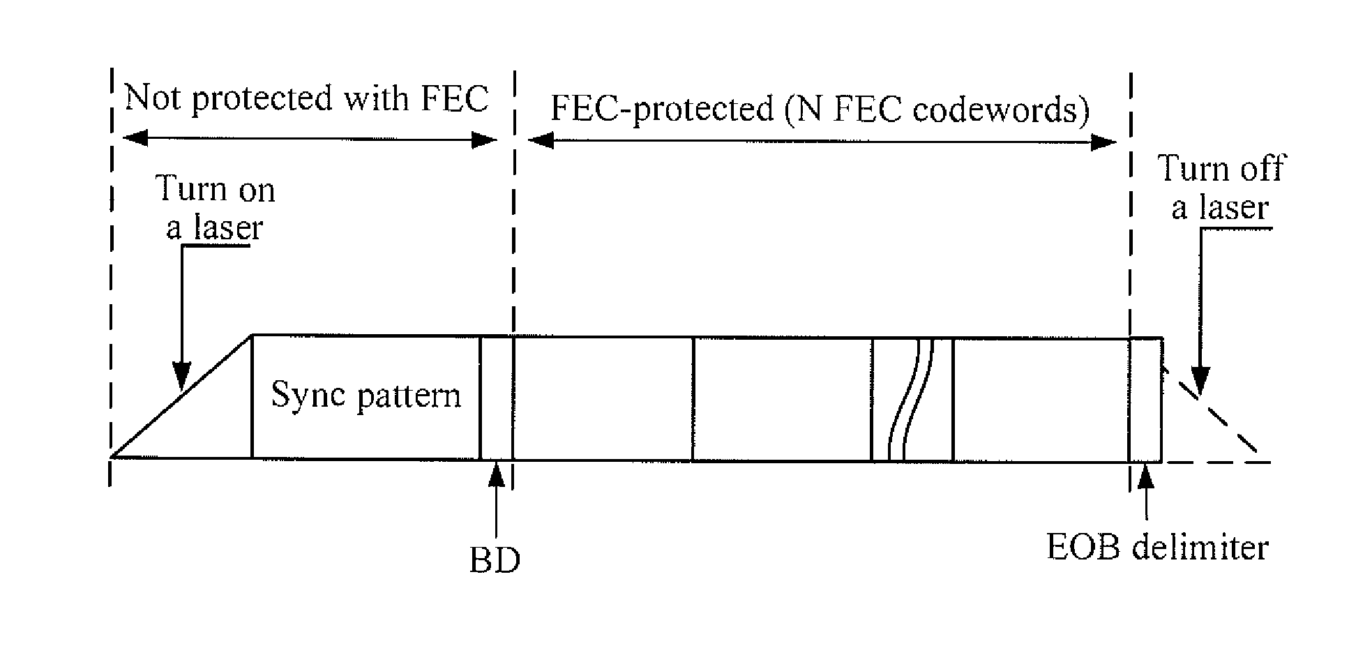
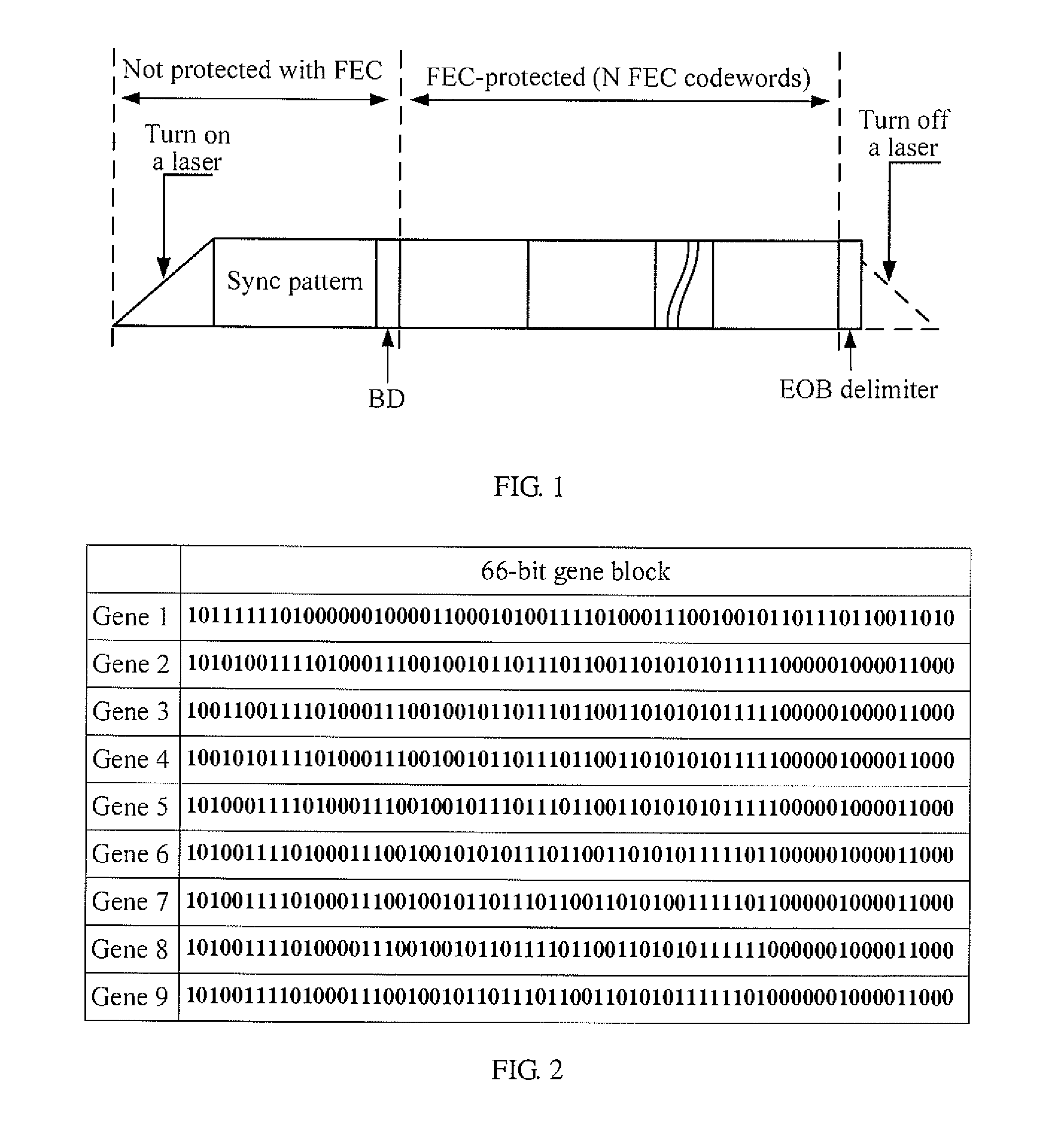
[0050]A technical solution will be described in an embodiment of the present invention taking a 10G Ethernet Passive Optical Network (10G EPON) system as an example. In the structure of burst data transmitted in the uplink according to the embodiment of the present invention as illustrated in FIG. 1, the uplink burst data transmitted from an ONU include a Synchronization pattern, a BD, an FEC-protected Ethernet data and an EOB delimiter. In particular, the synchronizati...


PUM


Abstract

A method for sending uplink burst data in a passive optical network (PON) system includes: sending a synchronization pattern of the uplink burst data, the synchronization pattern being of a length, which is an integer multiple of 66 bits, and being formed by connection of 66-bit unit gene blocks; sending a burst delimiter (BD) of the uplink burst data; sending a forward error correction (FEC)-protected data in the uplink burst data; and sending an end of burst (EOB) delimiter of the uplink burst data. The technical solutions in the embodiments allow the use of a less complex equalizer at the reception end of a high-speed PON system.

Description

CROSS-REFERENCE TO RELATED APPLICATIONS[0001]This application is a continuation of International Application No. PCT / CN2009 / 072290, filed on Jun. 16, 2009, which claims priority to Chinese Patent Application No. 200810068007.1, filed on Jun. 19, 2008, and to Chinese Patent Application No. 200910008103.1, filed on Mar. 2, 2009, and to International Application No. PCT / CN2008 / 073140, filed on Nov. 21, 2008, all of which are hereby incorporated by reference in their entireties.TECHNICAL FIELD[0002]The present invention relates to the field of Passive Optical Network (PON) technologies, and in particular to a method and device for sending uplink burst data in a PON.BACKGROUND[0003]The PON becomes a perfect optical access technology because of its advantages of being easy to maintain, a high bandwidth, a low cost, etc., which is an ideal physical platform to which various services of voice, data, video, etc., gain an integrated access through a single platform. The PON technology is an o...

Claims


Application Information

Patent Timeline
IPC IPC(8): G02F2/00H04L7/00H04B10/2581H04L1/00H04L7/08H04L12/44
CPCH04L7/041H04Q2011/0064H04Q11/0067H04B10/2581H04B10/27H04L1/00
Inventor GENG, DONGYUFENG, DONGNINGLI, JINGLEUNG, RAYMOND W.K.EFFENBERGER, FRANK
Owner HUAWEI TECH CO LTD
Learn More