
Hollow Fiber Membrane Module, and Method for Producing the Hollow Fiber Membrane Module

Inactive Publication Date: 2009-02-12
NOK CORP
View PDF4 Cites 6 Cited by
  • Summary
  • Abstract
  • Description
  • Claims
  • Application Information

AI Technical Summary

Benefits of technology

[0012]An object of the present invention is to provide a hollow fiber membrane module making it possible to make the structure thereof simple and further attain the reuse of a housing therefor, and a method for producing the hollow fiber membrane module.
[0031]According to the above-mentioned production method, it is possible to produce a hollow fiber membrane module which is not required to be equipped with a case or a head besides the housing for containing the hollow fiber membranes.
[0033]This manner makes it possible to take off from the hollow fiber membrane bundle from the jig without acting any tensile stress onto the hollow fiber membranes.
[0035]As described above, according to the invention, the structure can be made simple. Moreover, the housing can be reused.

Problems solved by technology

In the case of the injection molding, costs for the mold are high; in the case of the cutting work, costs for the raw material and the work are high.
In either case, these matters are large barriers against a decrease in costs.
In particular, in the case of using a hollow fiber membrane module as a humidifier in a fuel cell, costs for making a case therefor become high since the size of the hollow fiber membrane module is large.
In this case, costs are high as described above, and additionally the size or the shape of the case is actually restricted by the size or the shape of a round rod, a plate or the like that is a starting member of the raw material in many cases.
Furthermore, the case is partially cut after the seal-fixing material is hardened; therefore, the case is required to have a large cuttability.
Accordingly, in the case that the hollow fiber membranes therein deteriorate so that an exchange of the hollow fiber membrane module is required, the case cannot be reused.

Method used


Image

  • Hollow Fiber Membrane Module, and Method for Producing the Hollow Fiber Membrane Module
  • Hollow Fiber Membrane Module, and Method for Producing the Hollow Fiber Membrane Module
  • Hollow Fiber Membrane Module, and Method for Producing the Hollow Fiber Membrane Module

Examples


example 1

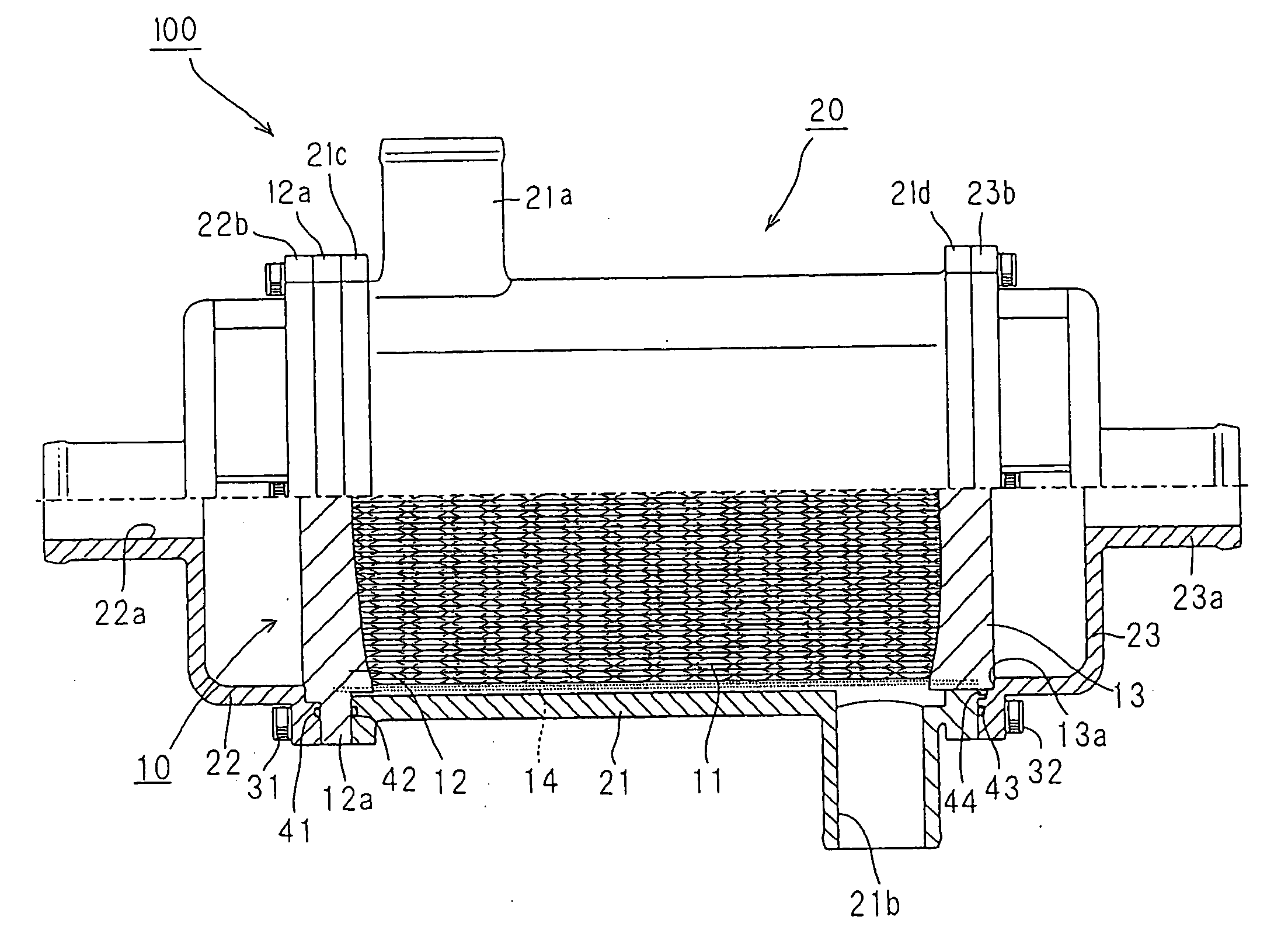
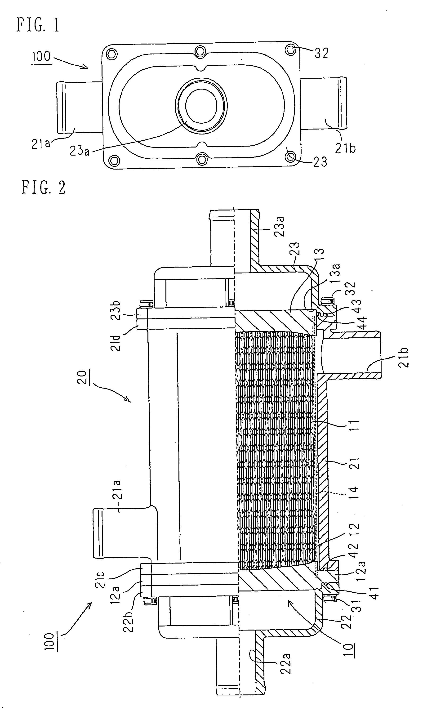
[0037]With reference to FIGS. 1 to 7, a hollow fiber membrane module and a method for producing the hollow fiber membrane module according to the example of the invention will be described.

[0038]

[0039]With reference to FIGS. 1 and 2, the hollow fiber membrane module according to the example of the invention is described. FIG. 1 is a plan view of the hollow fiber membrane module according to the example of the invention. FIG. 2 is a partially cutaway sectional view of the hollow fiber membrane module according to the embodiment of the invention when the module is viewed from the front thereof. In FIG. 2, the upper half is a front view, and the lower half is a sectional view.

[0040]The hollow fiber membrane module 100 according to the present example is composed of a hollow fiber membrane unit 10, and a housing 20 in which the hollow fiber membrane unit 10 is put. The hollow fiber membrane unit 10 is constructed to be freely put on and taken off from the housing 20.

[0041]The hollow fib...


PUM


Abstract

The structure can be made simple, and the reuse of a housing can be attained.A hollow fiber membrane module 100 including a hollow fiber membrane unit 10 which has plural hollow fiber membranes 11, and a first seal-fixing section 12 and a second seal-fixing section 13 for seal-fixing both ends of these hollow fiber membranes 11 to make the insides of the hollows therein open, and which is constructed in a state that outer wall faces of these seal-fixing sections are uncovered, and a housing 20 for containing the hollow fiber membrane unit 10, wherein the housing 20 has first ports 22a and 23a constituting a channel leading to the insides of the hollows in the hollow fiber membranes 11, and second ports 21a and 21b constituting a channel leading to the side of outer wall faces of the hollow fiber membranes 11, and the hollow fiber membrane unit 10 is constructed to be freely put on and taken off from the housing 22.

Description

BACKGROUND OF THE INVENTION[0001]1. Field of the Invention[0002]The present invention relates to a hollow fiber membrane module having plural hollow fiber membranes, and a method for producing the hollow fiber membrane module.[0003]2. Description of the Related Art[0004]About separating devices for separating water vapor or impurities from a fluid, such as humidifiers, dehumidifiers, or filter units, known are devices using a hollow fiber membrane module. With reference to FIGS. 8 and 9, two typical examples of hollow fiber membrane modules in the conventional art will be described. FIGS. 8 and 9 are each a schematic sectional view of a hollow fiber membrane module in the conventional art.[0005]First, the hollow fiber membrane module illustrated in FIG. 8 is described. The illustrated hollow fiber membrane module 500 is equipped with a module body 510 and a housing 520. The module body 510 has a case 511, plural hollow fiber membranes 512 contained in the case 511, and seal-fixing s...

Claims


Application Information

Patent Timeline
IPC IPC(8): B01D63/04
CPCB01D63/02B01D63/021Y02E60/50B01D2313/20H01M8/04149B01D65/00Y02P70/50B01D63/0233B01D63/0231B01D69/08B01D65/003B01D2313/205B01D2313/201B01D2313/04B01D2313/21B01D2313/08B01D2313/54B01D2313/02B01D2313/2062B01D63/0232
Inventor HAYASHI, TAKAHIRO
Owner NOK CORP
Learn More