Constant speed control system

a constant speed control and control system technology, applied in brake systems, process and machine control, instruments, etc., can solve the problems of surging and stopping of vehicles, affecting the actual speed of vehicles, and conventional systems that only work,

Active Publication Date: 2008-01-15
KELSEY HAYES CO
View PDF24 Cites 96 Cited by
  • Summary
  • Abstract
  • Description
  • Claims
  • Application Information

AI Technical Summary

Benefits of technology

[0010]The present invention has the advantage of maintaining a vehicle target speed where the vehicle target speed is determined from a predetermined speed versus accelerator pedal position curve in response to an acceleration pedal position regardless of the road surface incline or curvature. The vehicle target speed is preferably a relatively low speed, such as a low vehicle speed employed when maneuvering a vehicle to park it.

Problems solved by technology

Such tasks arise because often road surfaces have obstacles (i.e., trees, narrowed pathways, boat launch) which require the driver to concentrate on avoiding them more than on applying a respective force to the acceleration pedal.
But more times than not, too much acceleration force is applied and the driver must switch between the acceleration pedal and the brake pedal to maintain the desired speed, often resulting in surging and stopping of the vehicle.
These conventional systems typically only work when the vehicle is traveling above a certain threshold speed, such as forty-five miles per hour.
However, if the cruise control system is active while the vehicle is transitioning down an inclination, the actual vehicle speed may increase beyond that of the speed set by the cruise control.
The conventional cruise control system has no other self-means of reducing the actual speed of the vehicle to attain the lower vehicle target speed other than to reduce the torque of the engine.
When traveling at a relatively low speed, especially when maneuvering with a trailer, even if modified to work at low speeds, it is not practical to set buttons on these cruise control systems to maintain a constant speed.
Moreover, even at low vehicle speed, the driver cannot just move the accelerator pedal to a predetermined position to cause the vehicle to travel at a give rate of speed because the vehicle speed does not just depend upon the amount of engine torque but also on the incline of the road surface.

Method used


Image

  • Constant speed control system
  • Constant speed control system
  • Constant speed control system

Examples


Embodiment Construction

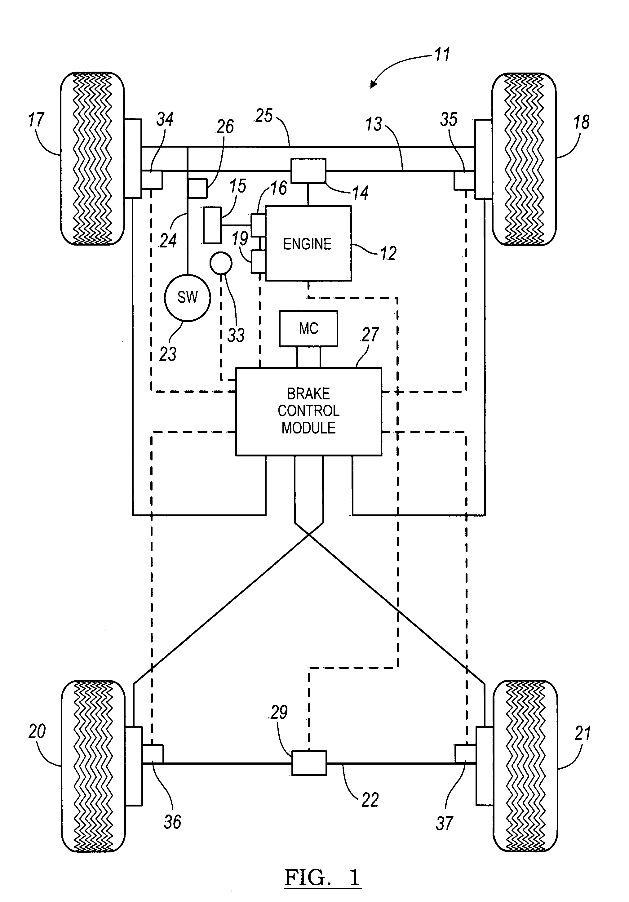
[0017]FIG. 1 illustrates an all wheel drive vehicle 11 according to a preferred embodiment of the present invention. The vehicle 11 includes an engine 12 that is coupled to front axles 13 via a transaxle 14. An accelerator pedal 15 provides an acceleration pedal demand signal to a throttle 16 of the engine 12. The throttle 16 controls the amount of air flow to the engine 12 for outputting a desired engine torque for driving the front left wheel 17 and the front right wheel 18. A powertrain control module (PCM) 19 adjusts the operating conditions of the engine 12 based on the current vehicle operating conditions and environmental conditions for optimizing the engine output. The engine 12 outputs an engine torque that is transferred to front vehicle wheels 17 and 18 via the transaxle 14. The transaxle 14 preferably includes a conventional differential subsystem that distributes engine torque between the front left and front right wheels 17 and 18. This also allows both front wheels 17...


PUM


Abstract

A method is provided for controlling a low speed operation of a vehicle. A speed activation switch is activated. A target vehicle speed is calculated in response to an accelerator pedal demand as determined by an accelerator pedal position where each respective accelerator pedal position is associated with a respective predetermined target vehicle speed. A vehicle turning geometry is determined in response to a steering wheel angle input. A target wheel speed of each of a plurality of vehicle wheels is calculated as a function of the target vehicle speed and turning geometry. An actual wheel speed of each wheel is measured. A net torque is determined in response to the target wheel speeds and actual wheel speeds. An engine output torque and a braking torque are determined in response to the net torque. The engine output torque and the total vehicle braking torque are controlled for cooperatively maintaining the target vehicle speed.

Description

CROSS REFERENCE TO RELATED APPLICATIONS[0001]Not Applicable.STATEMENT REGARDING FEDERALLY SPONSORED RESEARCH[0002]Not Applicable.BACKGROUND OF THE INVENTION[0003]1. Field of the Invention[0004]The present invention relates in general to speed control systems, and more specifically, to speed control systems for controlling speed through the use of engine torque and brake torque control.[0005]2. Description of the Related Art[0006]A driver of a vehicle while traveling along various roads, inclinations, or reversing a vehicle attached to a trailer may find themselves managing multiple tasks in addition to manipulating the accelerator and brake pedals to maintain a desired speed. Such tasks arise because often road surfaces have obstacles (i.e., trees, narrowed pathways, boat launch) which require the driver to concentrate on avoiding them more than on applying a respective force to the acceleration pedal. But more times than not, too much acceleration force is applied and the driver mu...

Claims


Application Information

Patent Timeline
Patent Type & Authority Patents(United States)
IPC IPC(8): G06F17/00B60K31/00
CPCB60W10/06B60W10/184B60W2720/28B60W30/143B60W2050/0011B60W2540/18
Inventor SUN, QIONGSCHIEB, ERICSPIEKER, ARNOLD H.WEBER, DAVID W.LUBISCHER, FRANK
Owner KELSEY HAYES CO
Why Eureka
Try Eureka