Cooling body

a technology of cooling body and heat sink, which is applied in the direction of cooling/ventilation/heating modification, semiconductor/solid-state device details, semiconductor devices, etc., can solve the problems of relatively high manufacturing cost of known heat sinks, and achieve the effects of convenient manufacturing, simple configuration, and easy manufacturing

Inactive Publication Date: 2006-05-30
ROBERT BOSCH GMBH
View PDF12 Cites 21 Cited by
  • Summary
  • Abstract
  • Description
  • Claims
  • Application Information

AI Technical Summary

Benefits of technology

[0003]In contrast to the related art, the heat sink according to the invention has the advantage that it is easier and more economical to manufacture. This is due to the fact that, given the configuration of the connecting means as a push-on connection having a projection on the main body, a main body shape is created that can be easily manufactured using an extrusion method (e.g., by joining). This is also due to the fact That, by configuring a mounting opening for the projection on The spring element, the opening edge of which bears, at least in sections, against the lateral surface of the projection under preload resulting from the intrinsic elasticity of the spring element and / or the projection, a spring element having a simple configuration can be provided. In terms of the push-on connection, an essential inventive idea is to utilize a property coming from the material of the spring element and / or the projection, namely the intrinsic elasticity, to produce the preload. Costly configurations of the spring element for producing a holding force on the projection can be avoided.
[0004]According to one embodiment of the present invention, configuration of the spring element is provided that is particularly simple and economical to manufacture.
[0005]According to one embodiment of the present invention, the advantage that the structural element is acted upon at a defined paint in a reproducible manner is created.
[0010]According to another embodiment, it is provided that the edge region of the mounting opening is provided with indentations to form spring tabs. The spring tabs provide the advantage that the mounting opening—as a result of the pushing-on motion—can be spread further apart, so that a greater lower deviation of the diameter of the mounting opening In the pre-installed state can be created. Since, as a result of the pushing-on motion, the spring tabs are bent radially outwardly against the direction of insertion, the advantage is also created that the push-on connection is prevented from coming loose, i.e., there is a safeguard against it slipping back off.
[0011]At the points that bear against the lateral surface of the projection in the installed state, the mounting opening edge can exert a force on the projection that is so great that a plastic material deformation is produced at these points (which form a contact zone) of the projection, and the contact zone is therefore configured as a plastic material deformation zone. The material deformation zone can be formed by notches, which are produced by the spring tabs “digging in”. By way of the plastic material deformation zone, it is possible to prevent the push-on connection from coming loose or sliding off, due to the creation of a form-fit connection between the mounting opening and the projection.

Problems solved by technology

Due to these previous means of fastening the spring element to the main body, the known heat sinks are relatively costly to manufacture.

Method used


Image

  • Cooling body
  • Cooling body
  • Cooling body

Examples


Embodiment Construction

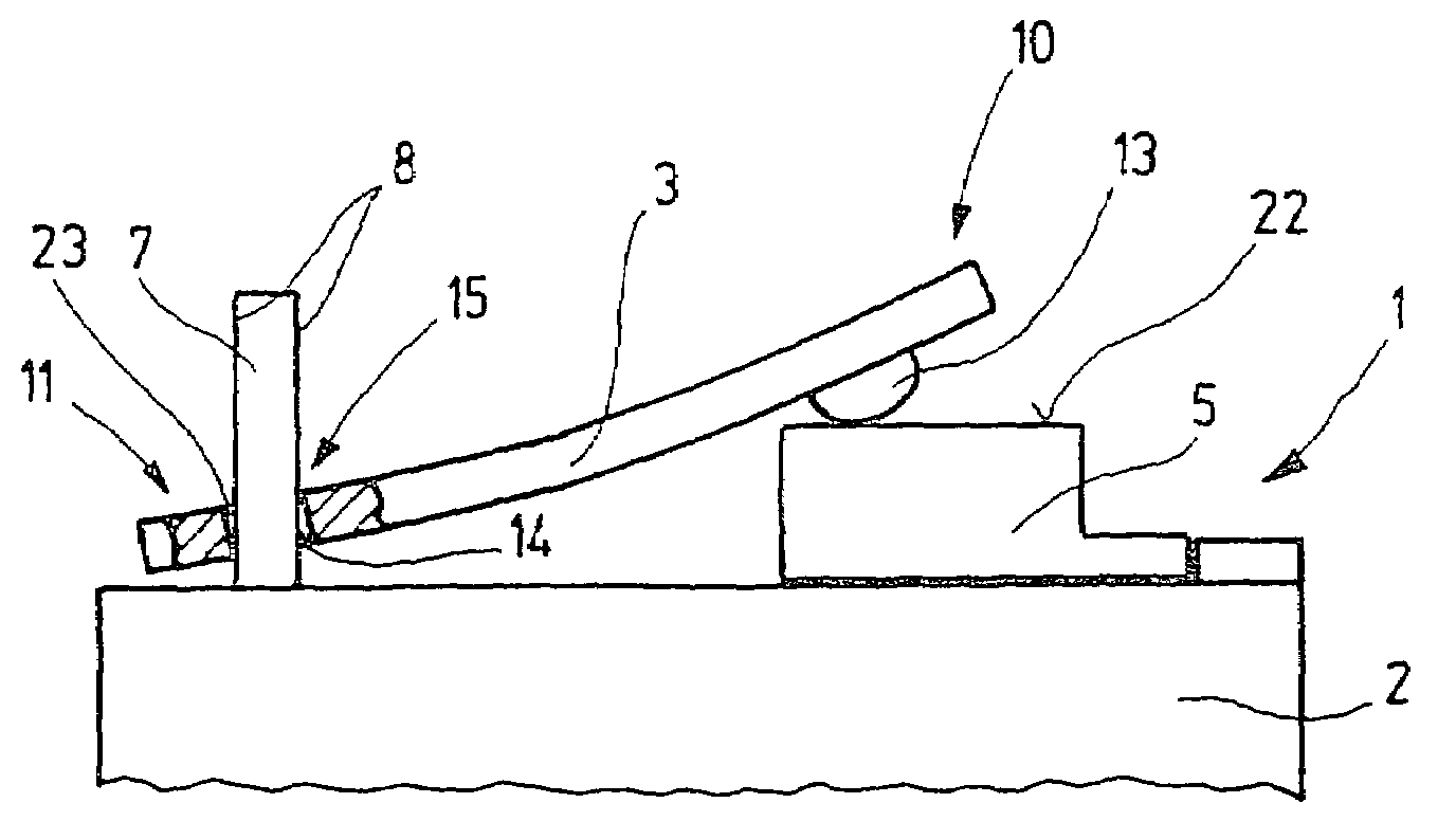
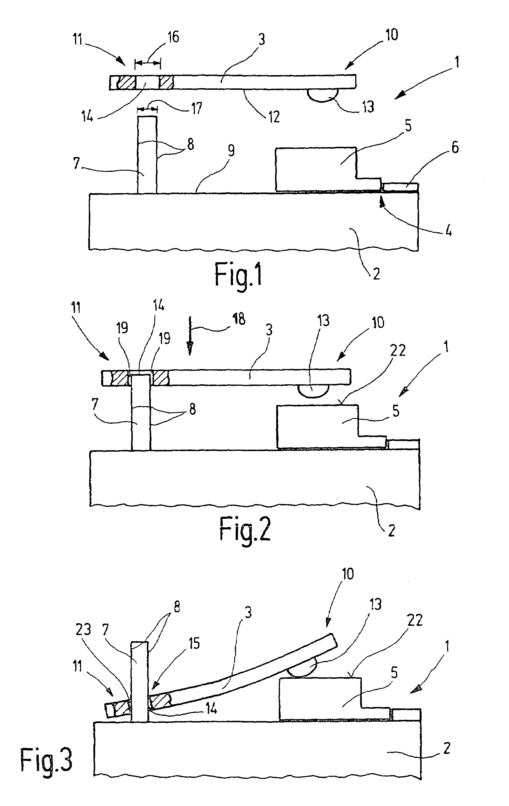
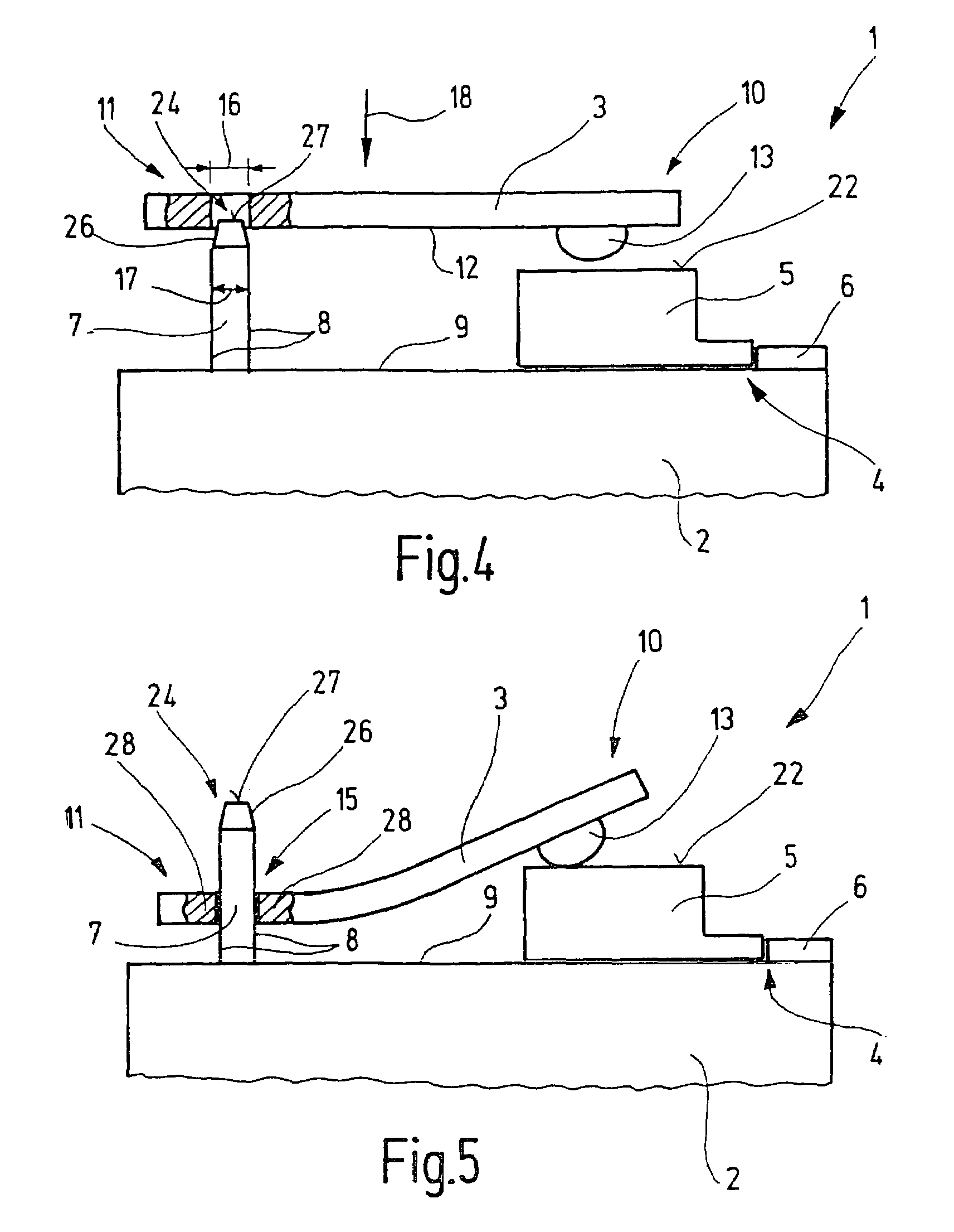
[0021]FIG. 1 shows, in a schematic representation, a heat sink 1 with a main body 2 and a spring element 3, before installation of spring element 3. Main body 2 has a receptacle 4 for accommodating an electronic structural element 5. Receptacle 4 of main body 2 contains a stop 6 for positioning structural element 5. Main body 2 further includes a projection 7 which extends, with its longitudinal side 8, at an angle of 90° and / or at an angle of essentially 90° to a top side 9 of main body 2. Spring element 3, which is configured as a leaf spring in the form of a flat spring, has a first end region 10 and a second end region 11, as viewed longitudinally. On its side 12 facing main body 2, first end region 10 contains a contact point 13 for electronic structural element 5.

[0022]In this exemplary embodiment, contact point 13 is configured as a projecting element opposite side 12 of spring element 3. The projecting element can be formed via material deformation of first end region 10 usi...


PUM


Abstract

The present invention relates to a heat sink (1) with a main body (2) for accommodating at least one electronic structural element (5), and with a spring element (3) for pressing the structural element (5) against the main body (2), whereby the spring element (3) is held on the main body (2) by a connecting means. It is provided that the connecting means are configured as a push-on connection (15) and have a projection (7) on the main body (2) and a mounting opening (14) in the spring element (3) for the projection (7), whereby the opening edge (23) of the mounting opening (14) bears, at least in sections, against the lateral surface of the projection (7) under preload resulting from the intrinsic elasticity of the spring element (3) and / or the projection (7).

Description

[0001]The present invention relates to a heat sink with a main body for accommodating at least one electronic structural element, and with a spring element for pressing the structural element against the main body, whereby the spring element is held on the main body by a connecting means.BACKGROUND INFORMATION[0002]Heat sinks of the type discussed here are known. They are used to absorb the heat dissipated from semiconductors in electronic circuits. To this end, the semiconductor is pressed onto a main body of the heat sink by a spring element. The spring element itself is held on the main body by latching into undercuts in the main body or being staked in a recess of the main body. Due to these previous means of fastening the spring element to the main body, the known heat sinks are relatively costly to manufacture.SUMMARY OF THE INVENTION[0003]In contrast to the related art, the heat sink according to the invention has the advantage that it is easier and more economical to manufac...

Claims


Application Information

Patent Timeline
Patent Type & Authority Patents(United States)
IPC IPC(8): H05K7/20H01L23/40
CPCH01L23/4093H01L2924/0002H01L2924/00
Inventor KIMMICH, PETER
Owner ROBERT BOSCH GMBH
Why Eureka
Try Eureka