Gimballed mechanical face seal

a mechanical face seal and gimbal technology, applied in the field of pumps, can solve the problems of high seal wear and frictional heat, virtually impossible deflection of seals, and inability to achieve symmetric loading and wear,

Inactive Publication Date: 2000-09-05
FREUDENBERG NOK GEN PARTNERSHIP
View PDF12 Cites 34 Cited by
  • Summary
  • Abstract
  • Description
  • Claims
  • Application Information

AI Technical Summary

Benefits of technology

Another object of the present invention is to provide a pump assembly that has a gimballed mechanism which allows more optimum seal spring pre-loads but still accommodates misalignments even when deflected solid through the gimballed mechanism.
Yet another advantage of the present invention is that it provides a gimbal mechanism which is easy and economical to manufacture which operates with improved efficiency.

Problems solved by technology

The problem with such pumps is that the positive hydraulic pressures developed within the pump work upon a hydraulic area within and effect the hydraulic diameter of the mechanical face seal which results in forces moving the impeller and compressing the seal axially further onto the pump motor shaft.
However, having such high spring forces creates higher than necessary seal wear and frictional heat because most of these pumps operate at considerably less than peak pressure 95% of their operating cycles.
However, on the other hand if a high spring load is not provided this will allow the impeller to slide on the shaft of the pump motor compressing the mechanical face seal until the seal is deflected to a solid position.
The solid position makes any further seal deflection virtually impossible.
With the seal in its solid position it would be unable to accommodate normal misalignments between the pump and motor or misalignments or non-parallel conditions within the pump components without causing non-symmetrical loading and wear of seal components whose flatness is critical in maintaining the sealing function.

Method used


Image

  • Gimballed mechanical face seal
  • Gimballed mechanical face seal
  • Gimballed mechanical face seal

Examples


Embodiment Construction

)

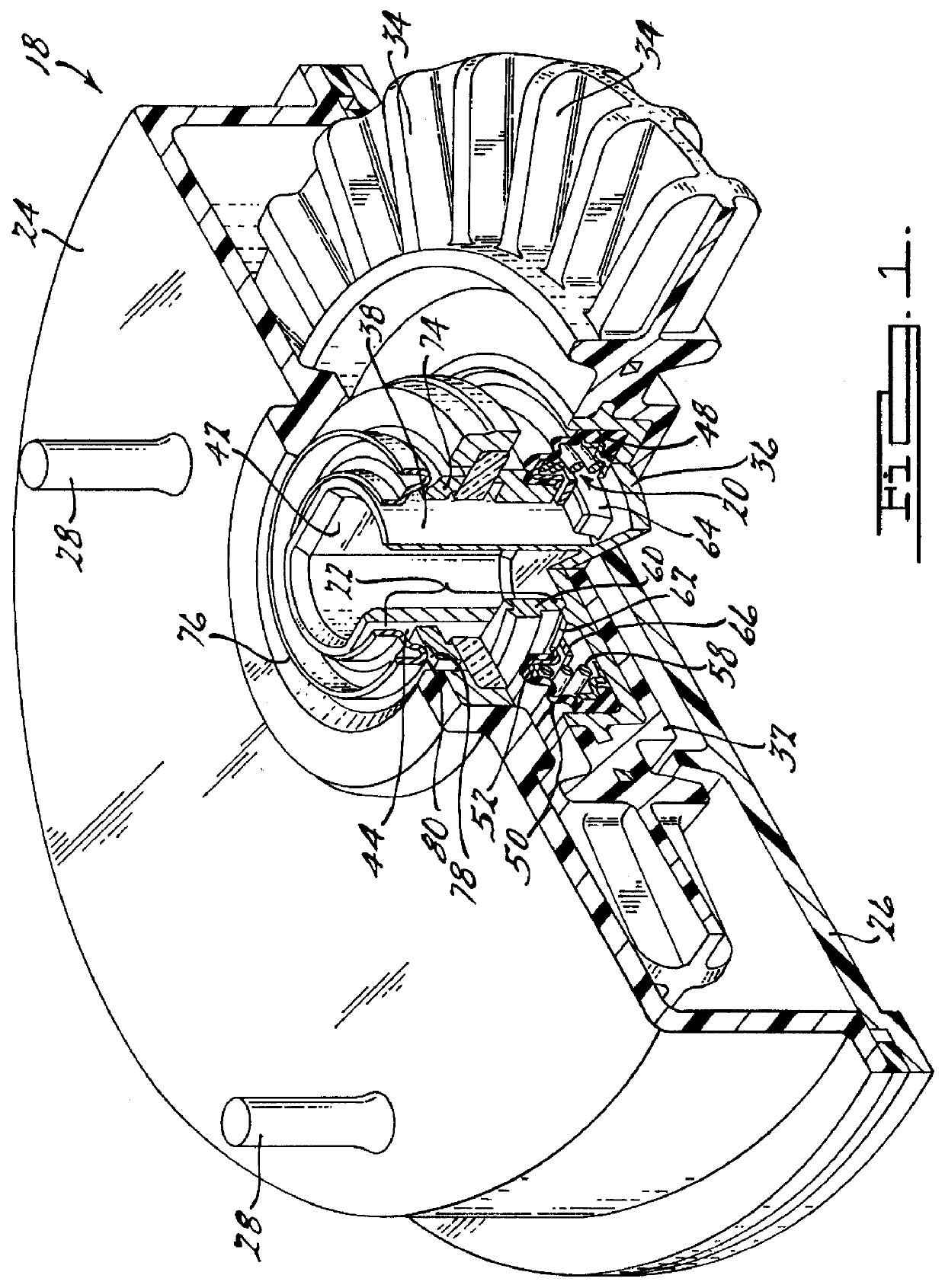
Referring to the drawings, a gimballed mechanical face seal 20 is disclosed. As shown in FIG. 1, a gimballed unitized seal, impeller, thrust system 22 is shown. Also shown is a pump housing 24 which has a generally U-shaped cross section and a pump cover 26 which connects via welding or other fastening means to the pump housing 24 thus creating the pump for use in appliances such as dishwashers, laundry machines, and the like. The pump cover 26 and the pump housing 24 in the preferred embodiments are made of a filled thermoplastic material however it should be noted that any other hard rigid material may be used such as metals or thermoset plastic type materials. The pump housing 24 also has leg members 28 mounted on or molded into its outer casing which are used to mount the pump to an electric motor 30 or other motorized device.

The pump includes an impeller assembly 32 having a plurality of blades 34 with contoured ends. The impeller 32 forms a circular plate-like shape as shown ...


PUM


Abstract

A mechanical face seal for use in a pump. The mechanical face seal including a seal head assembly, a seal seat assembly opposite and in contact with the seal head assembly. The seal head assembly including a gimbal ring engaging a first and second pair of gimbal pads. The first pair of gimbal pads is integral with an impeller insert and the second pair of gimbal pads is integral with a seal washer. The gimbal ring will continually adjust to misalignments of the pump and the seal components when hydraulic forces overcome the spring load of the seal head assembly and clamps the gimbal ring between the two pair of gimbal pads.

Description

1. Field of the InventionThe present invention relates to pumps, and more particularly to a gimballed mechanical face seal for use in a pump.2. Description of Related ArtMany appliances used today such as dishwashers, laundry machines, etc., use water pumps that have an impeller that is rotationally driven by a pump motor shaft through rotational locks, such locks can be corresponding flats in the impeller and on the shaft of the motor. However, many of these impeller shaft combinations are free to move axially along the shaft due to radial clearances between the impeller and the shaft. Many of the pumps found in current day appliances use an impeller with a cup shaped recess that fits around but not against the bottom of the end of the motor shaft. This allows substantial clearance between the bottom of the cup shaped recess and the end of the motor shaft and accommodates significant end play of the motor shaft and also accommodates axial tolerances in mounting the pump housing to ...

Claims


Application Information

Patent Timeline
Patent Type & Authority Patents(United States)
IPC IPC(8): F04D29/08F16J15/36F04D29/12
CPCF04D29/126F16J15/36
Inventor DAHLHEIMER, JOHN C.
Owner FREUDENBERG NOK GEN PARTNERSHIP
Why Eureka
Try Eureka