Method and apparatus for supporting an insulated pipe

a technology of insulating pipe and supporting wall, which is applied in the direction of mechanical equipment, machine supports, other domestic objects, etc., can solve the problems of insufficient strength of insulating pipe surrounding wall, inconvenient installation, and inability to meet the requirements of use, etc., to achieve economic and easy manufacturing and installation

a technology of insulating pipe and supporting wall, which is applied in the direction of mechanical equipment, machine supports, other domestic objects, etc., can solve the problems of insufficient strength of insulating pipe surrounding wall, inconvenient installation, and inability to meet the requirements of use, etc., to achieve economic and easy manufacturing and installation

US7213790B2Active Publication Date: 2007-05-08PIPING TECHNOLOGY AND PRODUCTS

Image

  • Method and apparatus for supporting an insulated pipe
  • Method and apparatus for supporting an insulated pipe
  • Method and apparatus for supporting an insulated pipe

Examples


Embodiment Construction

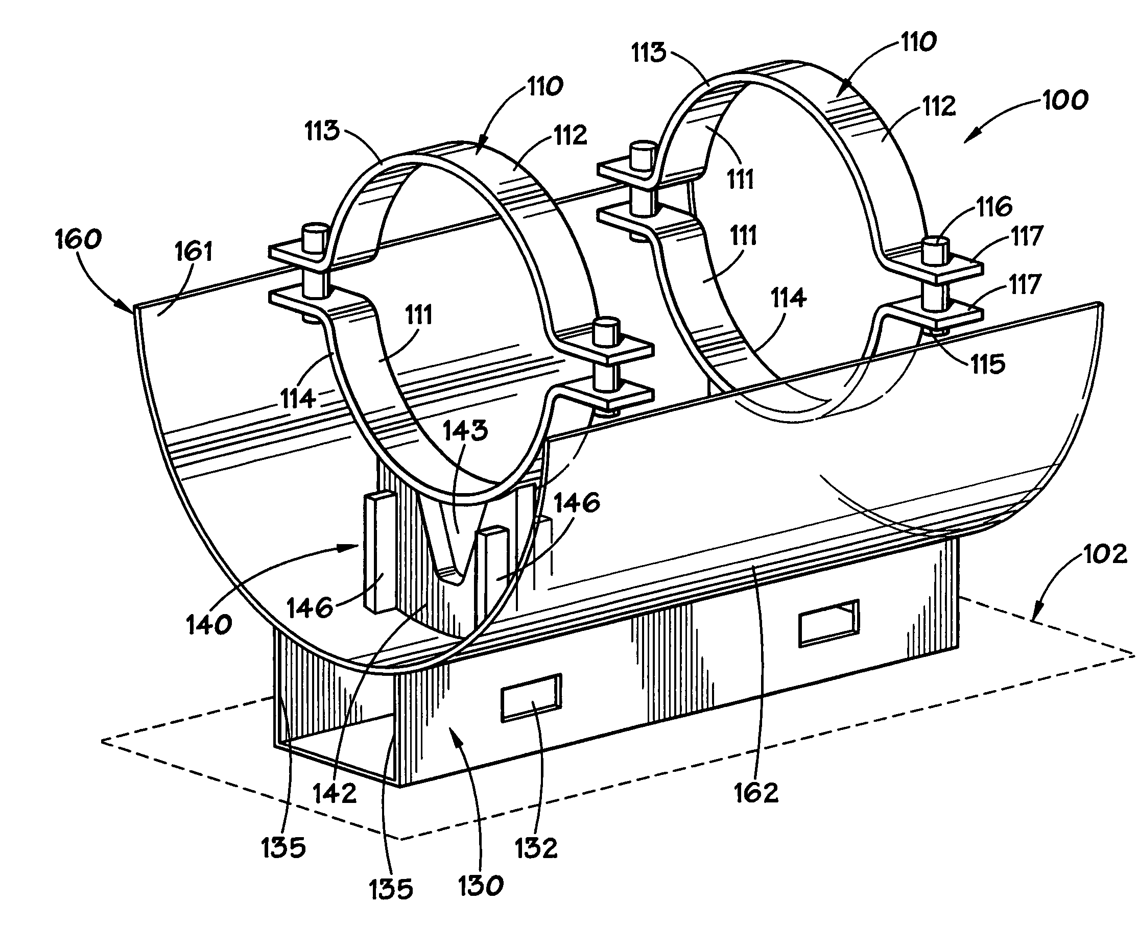
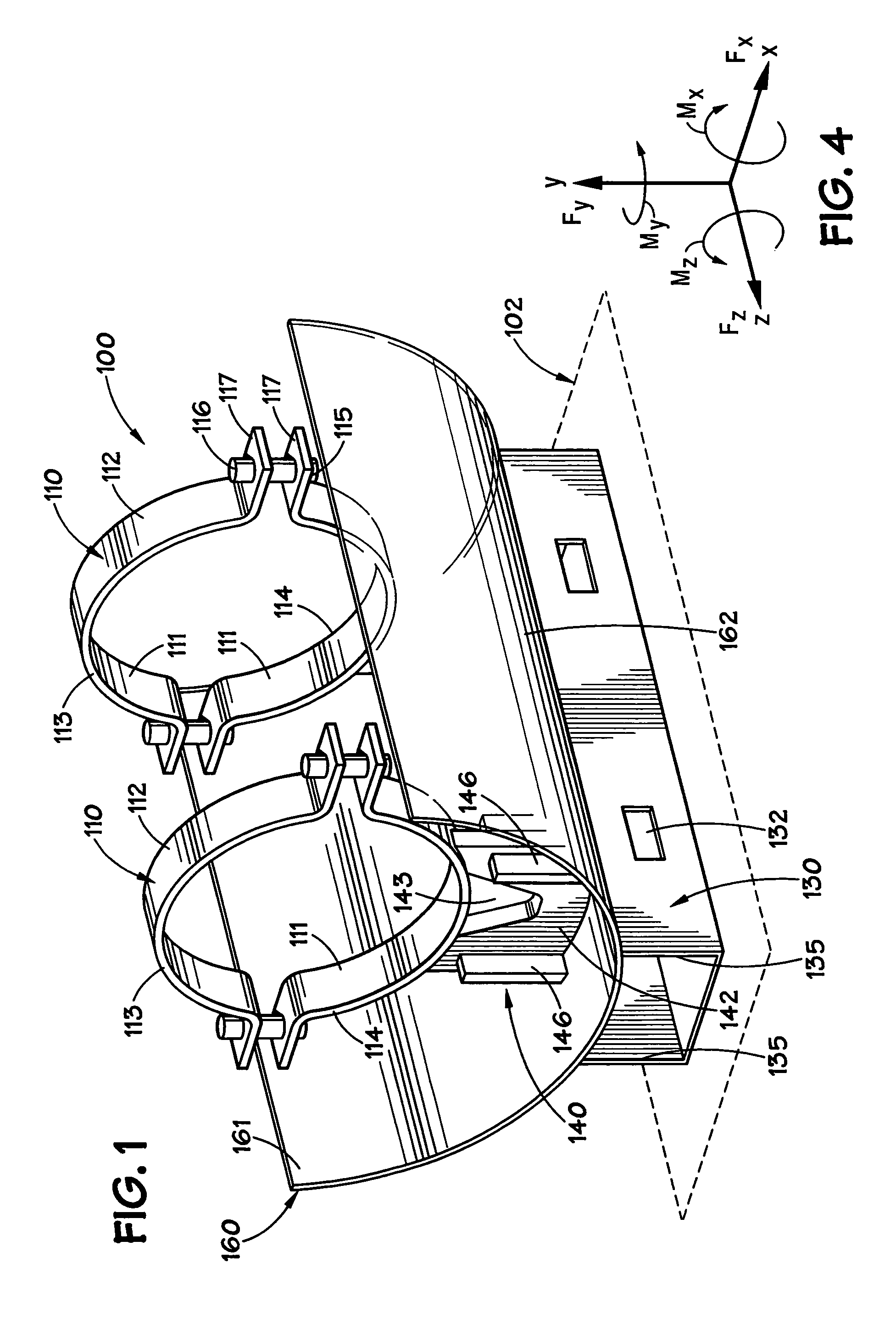
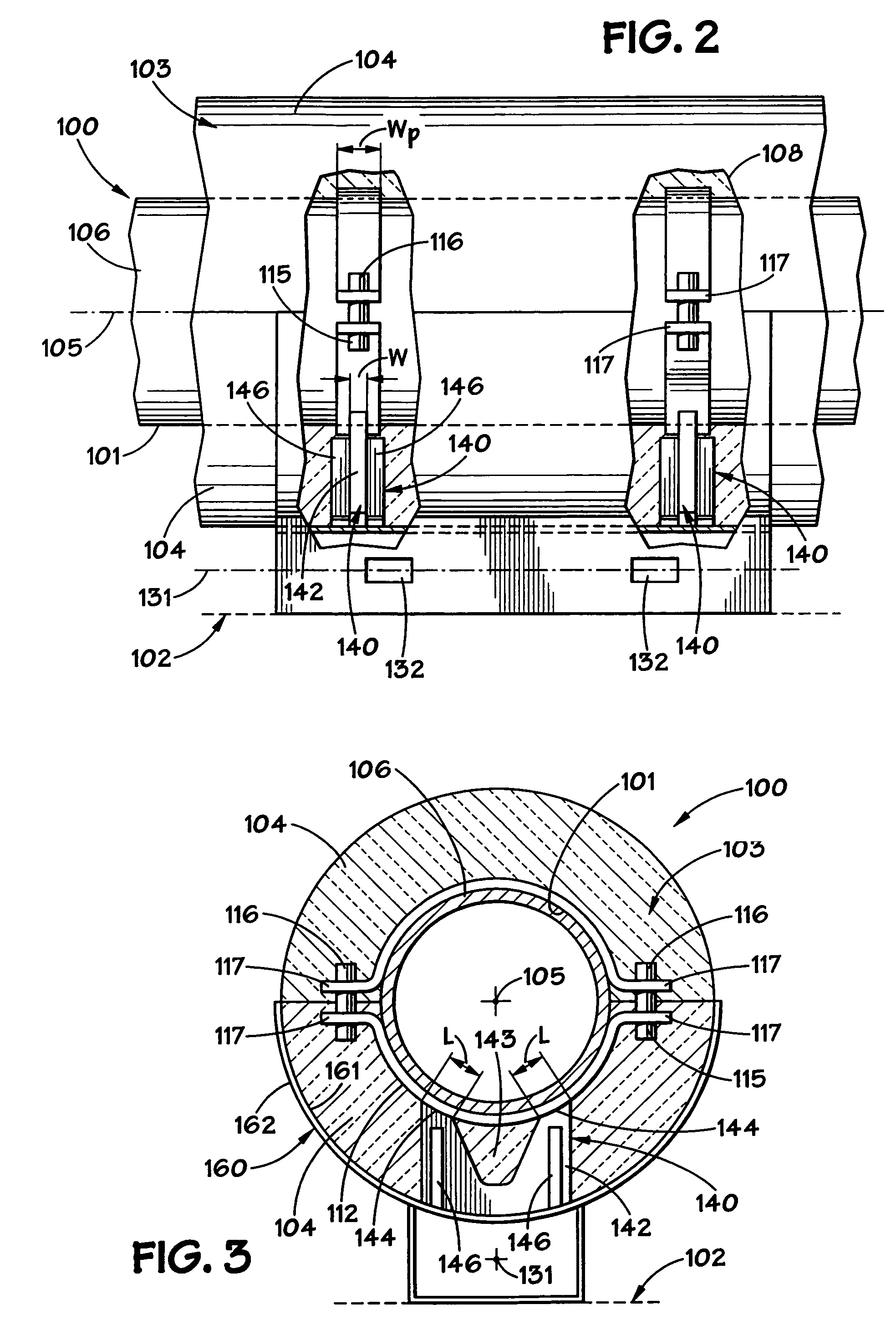
[0024]With reference to FIGS. 1–3, an apparatus 100 for supporting a portion of a length of pipe 101 (FIGS. 2 and 3) by a girder, beam, floor, or other support structure, shown in phantom lines 102, is illustrated. For ease of illustration, pipe 101 and insulation material 103 are not illustrated in FIG. 1. Pipe 101 has a longitudinal axis 105, an outer wall surface 106, and insulation material 103 is generally associated with substantially all of the outer wall surface 106 of the length of pipe 100. For ease of illustration, as will hereinafter be described in greater detail, a portion of apparatus 100 and insulation 103 is removed, as shown at phantom lines 108.

[0025]With reference to FIG. 4, the six components of load, or loads, from pipe 101 are diagrammatically illustrated as the forces Fx, Fy, and Fz, which are forces exerted in the direction of the x, y, and z axes, as is known in the art. The other three components of load, are the moments Mx, My, and Mz, or torsional, or tw...


PUM


Abstract

A method and apparatus for supporting a portion of a length of insulated pipe by a girder or other support structure, includes at least two pipe clamps, a base member, and a load transfer member attached to each of the at least two pipe clamps, wherein substantially none of the load, or forces and moments, exerted by the pipe, are carried, or transmitted, by the insulation disposed about the pipe.

Description

RELATED APPLICATIONS[0001]Applicants claim the benefit of U.S. Provisional Patent Application 60 / 508,090 filed Oct. 2, 2003.BACKGROUND OF THE INVENTION[0002]1. Field of the Invention[0003]The invention relates to a method and apparatus for supporting an insulated pipe, and in particular insulated pipes for cryogenic and high temperature applications[0004]2. Description of the Related Art[0005]In the construction of various types of facilities, such as nuclear power plants, oil refineries, chemical plants, petrochemical plants, gas liquification plants, and power generating plants, pipes are used to carry high and low temperature gases and liquids, such as steam, chilled water, or very cold, or cryogenic, fluids. These pipes are typically provided with insulation, such as layers of insulation batts, blown-in or loose insulation, or foam insulation surrounding the pipe to reduce heat loss from the heated fluid within the pipe, or to reduce heat gain to the fluid or gas within the pipe...

Claims


Application Information

Patent Timeline
08 May 2007
Publication
US7213790B2
IPC
F16L3/08; F16L3/10; F16L3/24; F16L59/14
CPC
F16L3/1016; F16L3/24; F16L59/135; F16L59/141
Inventors
BAILEY, RANDY J.; EARLE, EDWARD N.