Optical system with reflectors and light pipes

a technology of optical system and light pipe, which is applied in the direction of optical elements, lighting and heating apparatus, instruments, etc., can solve the problems of mercury disposal, large environmental impact, and large consumption of fluorescent lamps, and achieves the effect of easy and economical manufacture and simple construction

Inactive Publication Date: 2012-10-30
RAMBUS DELAWARE
View PDF104 Cites 33 Cited by
  • Summary
  • Abstract
  • Description
  • Claims
  • Application Information

AI Technical Summary

Benefits of technology

[0016]Another advantage of the present invention is that a device that distributes light over a large area can still be contained in a very thin package.
[0017]Yet another advantage of optic system of the present invention is that it is simple in construction, and therefore easy and economical to manufacture.
[0018]These and other objectives and advantages of the present invention will become apparent to those skilled in the art in view of the description of the best presently known mode of carrying out the invention as described herein and as illustrated in the drawings.

Problems solved by technology

However, with the mass implementation of fluorescent fixtures came mass consumption of fluorescent lamps.
Disposal of expended fluorescent lamps has become a big environmental problem due to the fact that mercury is required for use in the fluorescent tubes, and disposal of mercury has a large environmental impact.
The environmental issue and other disadvantages inherent to fluorescent lighting have led to the prospective development of LEDs as an alternative lighting source.
One drawback to prism films is that they have only limited control of the angle of the light output.
Further, changes to the prism features result in only slight variations in the light output.
The prism films are also limited to an essentially two dimensional structure.
But a drawback to the Yamaguchi device is that it is extremely inefficient.
Even when the reflective surface is made with a high reflectance material, the losses in intensity are substantial.
Therefore while the control of light with a Yamaguchi type device is superior to that of BEF devices, the efficiency of the device is very low.
The range of control of these reflective structures is limited, and the control is not equivalent to that provided by devices such as Yamaguchi.
Although this type of system is effective in collecting all of the light from the LED, the ability to control the output is limited.
Therefore if a particular application requires a cone angle of less than 41 degrees, this system cannot be used.
Another drawback inherent to the system of FIG. 1 is due to the fact that the output light comes from two sources, a lens and a reflector.
It is therefore very difficult to optimize the output from both sources simultaneously.

Method used


Image

  • Optical system with reflectors and light pipes
  • Optical system with reflectors and light pipes
  • Optical system with reflectors and light pipes

Examples


Embodiment Construction

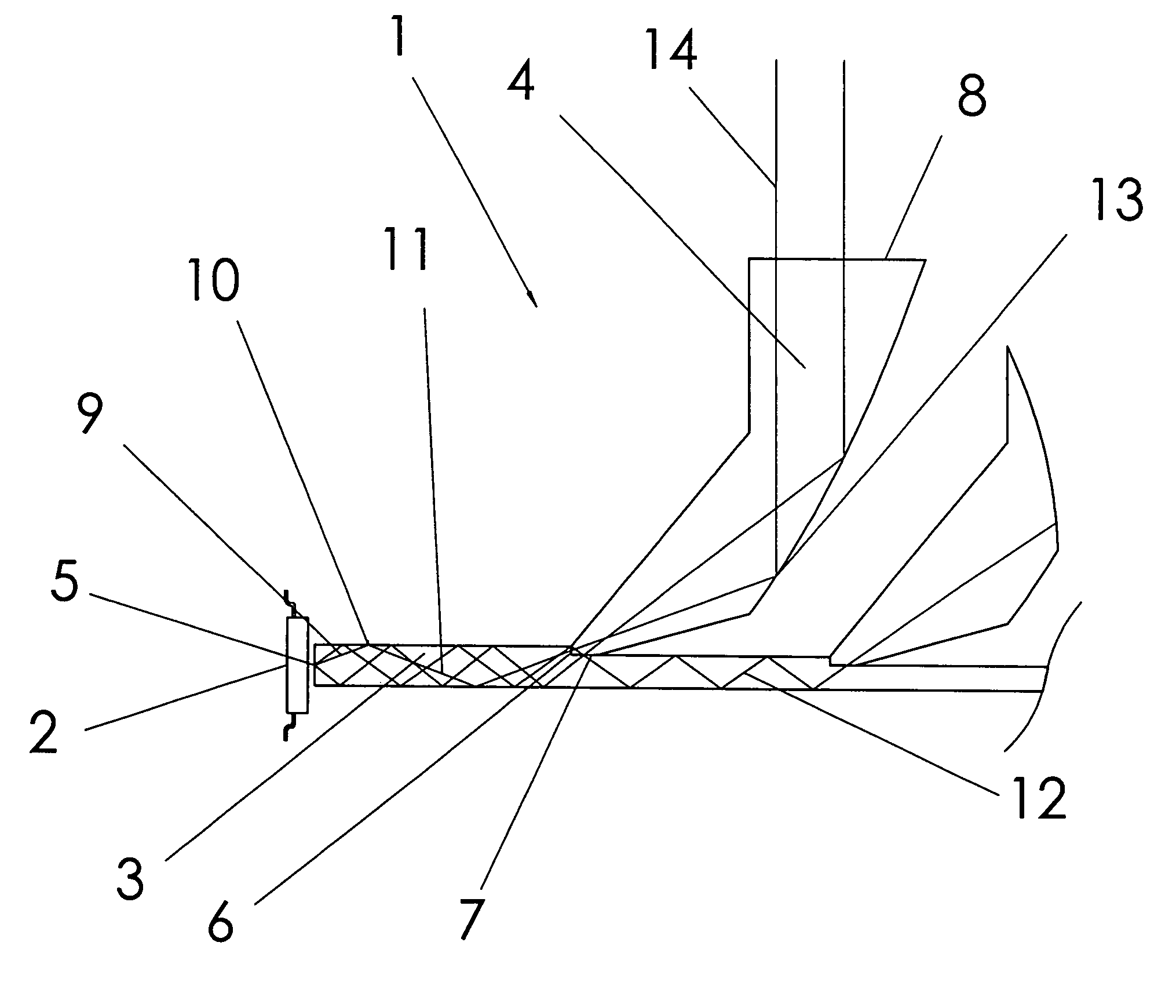
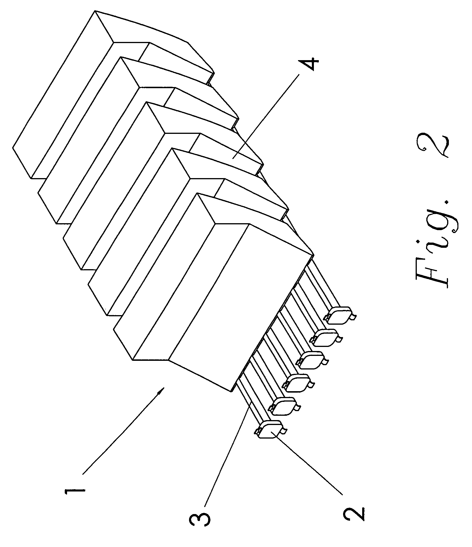
[0031]Referring first chiefly to FIG. 2, the optical system 1 of the present invention comprises a plurality of LEDs 2 situated at a first end 5 of a plurality of light pipes 3. It should be noted that more than one LED 2 could be associated with each light pipe 3. It should also be noted that the drawing is not to scale. The LED 2 would be much smaller, or the light pipe 3 could be wider, than depicted in the drawings.

[0032]For some applications, such as when the desired output of the system 1 is the projection of differing colors, multiple LEDs 2 are employed on each light pipe 3 as illustrated in FIG. 2B. At least one sensor is positioned so as to monitor the light pipes 3 to determine the actual color or colors being produced by the LEDs 2. Controlling electronics monitor the output from the sensors and drive the LEDs 2 to control the color of the output light as desired for the application. DMX is one industry standard protocol that can be used to drive the controlling electron...


PUM


Abstract

An optical system utilizing a light pipe in which light travels by total internal reflection (TIR) accurately controls the light exiting the pipe. The system achieves accurate control of the reflected light by selectively extracting light from a limited area of the light pipe. The configuration of the reflectors used for the selective extraction of the light determines the nature of the output light. The reflectors are preferably located on an output side of the light pipe. All light output by the system is directed by the reflectors.

Description

FIELD OF THE INVENTION[0001]The present invention relates generally to light collection devices, and more particularly is a light pipe optical system that collects light from a light source and distributes the light over a large area, while precisely controlling the angle and distribution of the illuminant within the output light beam. The unique optical system allows the device to be manufactured in extremely thin packages.BACKGROUND OF THE INVENTION[0002]Many products require an optical system that is capable of spreading light over a large area and controlling the direction of the light as it exits the system. Recent improvements in the performance of LEDs, coupled with a concurrent reduction in the cost of their production, have made LEDs a more viable option for many applications. However, many applications such as LCD backlights, signs with backlights, overhead lighting, and automotive lighting require the concentrated light that is generated by an LED to be spread over a larg...

Claims


Application Information

Patent Timeline
Patent Type & Authority Patents(United States)
IPC IPC(8): F21V7/04
CPCG02B6/0028G02B6/0075G02B6/0053
Inventor RICHARDSON, BRIAN EDWARD
Owner RAMBUS DELAWARE
Why Eureka
Try Eureka