Adapter stand for use with a buoyant waterfowl decoy, kit including the adapter stand, and method of using same

a technology for adapters and waterfowl, applied in the field of adapters for use with buoyant waterfowl decoys, can solve the problems of not knowing any prior art, unable to use decoys designed for land use in water applications, and unable to meet the needs of waterfowl hunting, so as to reduce the cost of equipment and reduce the transportation and storage requirements of this equipment.

Inactive Publication Date: 2005-12-08
EASTMAN HLDG
View PDF99 Cites 36 Cited by
  • Summary
  • Abstract
  • Description
  • Claims
  • Application Information

AI Technical Summary

Benefits of technology

[0014] The present invention provides a decoy adapter stand which allows a floatable buoyant decoy to be adapted for use on land, thus allowing a hunter to use a single decoy in different environments. When usi

Problems solved by technology

It is also difficult to use decoys designed for land use in water applications.
This incurs both increased cost and inconvenience, since multiple decoys must be stored, maintained, and transpor

Method used


Image

  • Adapter stand for use with a buoyant waterfowl decoy, kit including the adapter stand, and method of using same
  • Adapter stand for use with a buoyant waterfowl decoy, kit including the adapter stand, and method of using same
  • Adapter stand for use with a buoyant waterfowl decoy, kit including the adapter stand, and method of using same

Examples


first embodiment

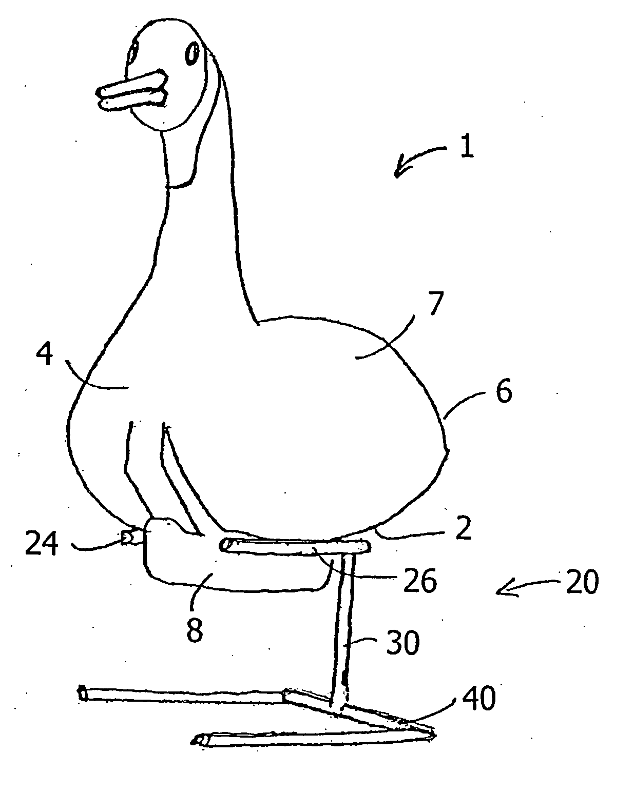
[0034] As best seen in FIG. 5, the invention is a freestanding adapter stand 20 that includes an upper bracket 22, a spacer 30, and a footed base 40. A decoy 1 is shown mounted on and supported by the bracket 20 in FIG. 9.

[0035] The upper bracket 22 of the adapter stand 20 is used to interconnect the floatable buoyant decoy 1 and the decoy adapter stand 20. The upper bracket 22 is a bifurcated elongate rod formed into a V-shape, such that it has a first tine 24 and a second tine 26. The first tine and second tines 24, 26 intersect at an apex 28, and extend substantially perpendicularly to the spacer 30, such that the upper bracket 22 generally lies in the horizontal plane. Preferably, the first tine 24 and the second tine 26 are each provided in a length which is at least half the length of a decoy.

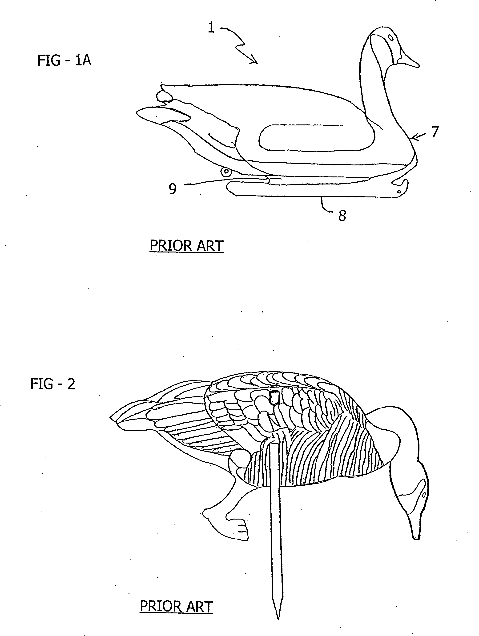
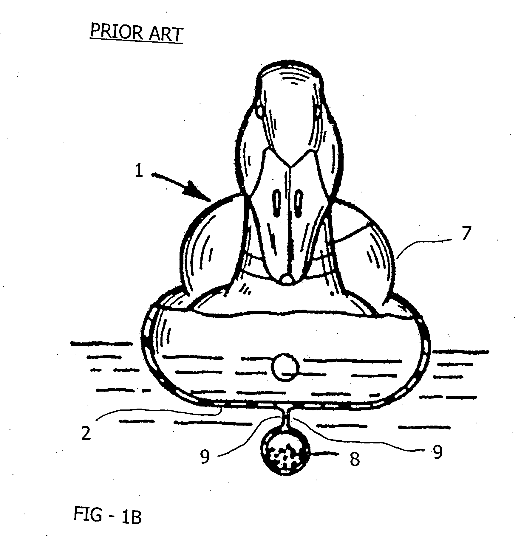
[0036] In use, the upper bracket 22 is aligned with and placed in back of the keel 8, and the tips of the respective tines 24, 26 are placed in the channels 9 on opposite sides of the ke...

second embodiment

[0044] Referring now to FIGS. 4 and 7, the invention will now be described. Staked decoy adapter stand 70 includes an upper bracket 72, a spacer 80, and a staked base 90. The upper bracket 72 is formed into a V-shape, such that it has a first tine 74 and a second tine 76 that intersect at an apex 78. The spacer 80 has an upper end 82 and a lower end 84. The spacer 80 and upper bracket 72 are identical to the components described above with respect to the footed, freestanding decoy adapter stand 20.

[0045] The staked base 90 is provided for anchored insertion within the ground, and functions to support and stabilize the upper bracket 22 and the spacer 30. The staked base 90 includes an anchor stake 98 and a stabilizer arm 92. Anchor stake 98 extends downwardly from lower end 84 of the spacer 80, and may be tapered adjacent its terminal end, such that the terminal end is pointed. The exterior surface of the anchor stake 98 may, optionally, be provided with external threads on the tip o...


PUM


Abstract

A decoy adapter stand allows a floatable buoyant waterfowl decoy to be adapted for use on land. The decoy adapter stand includes an upper securing bracket, a base, and a vertical spacer joining the upper bracket to the base. The securing bracket is used to secure a floatable buoyant waterfowl decoy to the stand, and the base provides a stable support. In use, the vertical spacer distances the decoy from the surface of the ground, so that the decoy appears to be standing. A first, freestanding embodiment of the decoy adapter stand includes a footed base. A second embodiment of the decoy adapter stand includes a staked base, where portions of the base are insertable into the ground. A method of using the described apparatus to adapt a floatable buoyant decoy for land use is also described.

Description

CROSS-REFERENCE TO RELATED APPLICATIONS [0001] The present invention claims priority under 35 USC 119(e) based on U.S. provisional patent application No. 60 / 574,244, filed May. 25, 2004.BACKGROUND OF THE INVENTION [0002] 1. Field of the Invention [0003] The present invention relates to waterfowl decoys and related accessories. More particularly, the present invention relates to an adapter stand, which is usable with a buoyant waterfowl decoy, to allow a hunter to adapt the waterfowl decoy for land use. The present invention also relates to a kit including the novel adapter stand and a buoyant waterfowl decoy, as well as to a method of using the described adapter stand to modify and adapt a buoyant waterfowl decoy for land use. [0004] 2. Background Art [0005] A variety of animal decoys are known and used by hunters, for placement in field environments to attract wild game. Many different decoys are known for simulating many different types of animals, in many types of environments. [...

Claims


Application Information

Patent Timeline
IPC IPC(8): A01M31/06
CPCA01M31/06
Inventor FOSTER, DAVID LARRYBUTCHER, ROBERT
Owner EASTMAN HLDG
Why Eureka
Try Eureka