Quick connect assembly

a technology of electrical connectors and assembly parts, applied in the direction of coupling device connections, lighting support devices, lighting and heating apparatus, etc., can solve the problems of time-consuming and time-consuming installation or uninstallation of such fixtures, and achieve the effect of fast connection, speeding up manufacturing and assembly of devices, and reducing the cost of devices

Inactive Publication Date: 2009-11-12
KOHEN RAN
View PDF3 Cites 60 Cited by
  • Summary
  • Abstract
  • Description
  • Claims
  • Application Information

AI Technical Summary

Benefits of technology

[0007]According to one aspect of the invention, a device is provided for quickly connecting an electrical fixture with electrical power supply wiring, and for mounting the fixture on a support. The device includes a socket including a socket body having at least one internal cavity therein; an electrically conductive contact terminal disposed within the cavity for establishing an electrical connection between the electrical power supply wiring and the socket, the contact terminal having a portion thereof captured between internal surfaces of the socket body to hold the contact terminal in a fixed position without the need for fasteners; a plug rigidly fixed to the fixture and insertable into the socket, the plug having at least one male connector electrically connected to the fixture and engageable with the contact terminal within the socket to establish a circuit between the electrical fixture and the electrical power wiring; and, a releasable latch carried on the combination of the plug and the socket for releasably mounting the fixture on the support. The elimination of fasteners to hold the contact terminal in place not only reduces the cost of the device but also speeds manufacturing and assembly of the device.

Problems solved by technology

The procedure for installing or uninstalling such fixtures can also be relatively time consuming, even when performed by an experienced installer.

Method used


Image

  • Quick connect assembly
  • Quick connect assembly
  • Quick connect assembly

Examples


Embodiment Construction

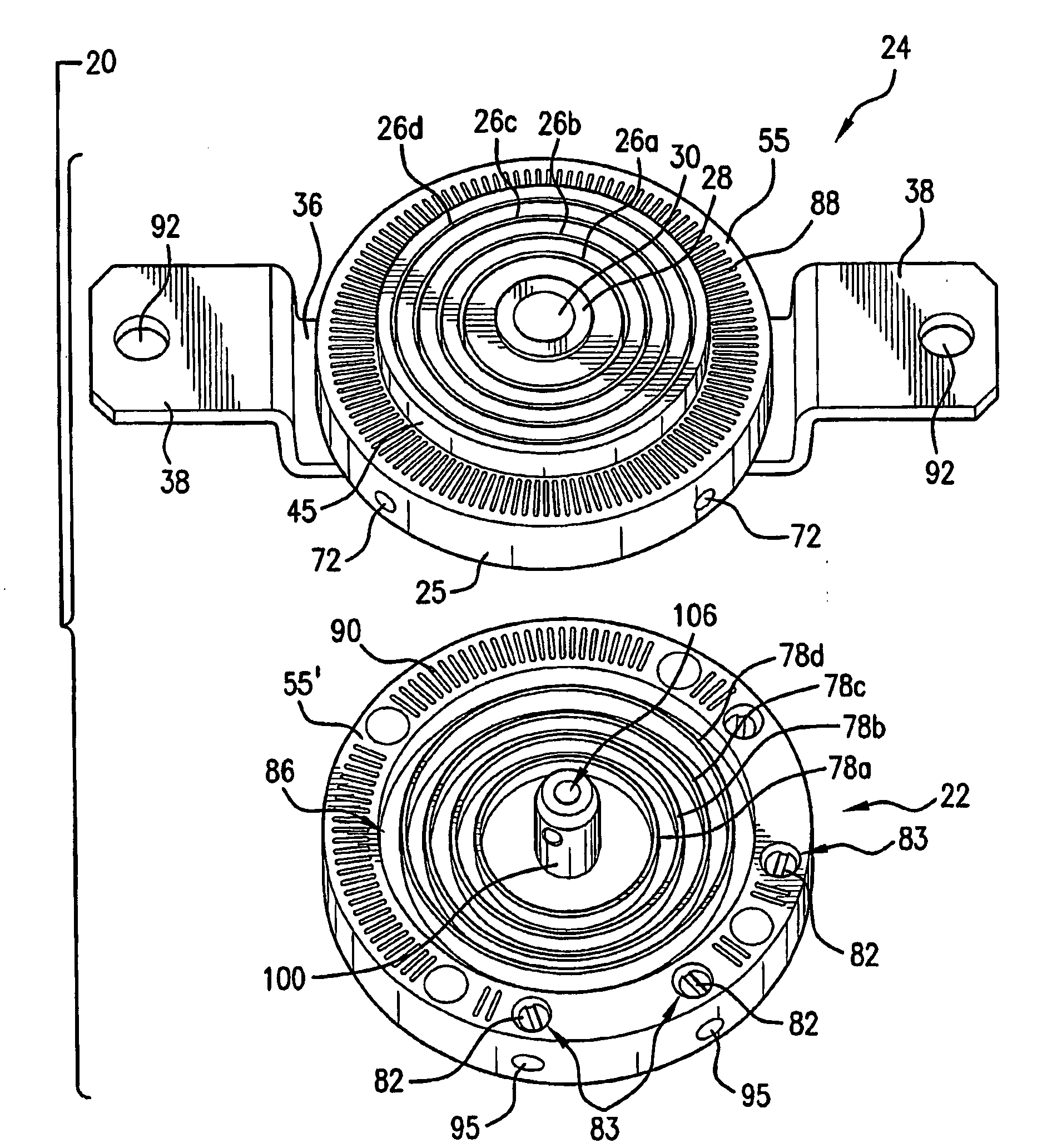
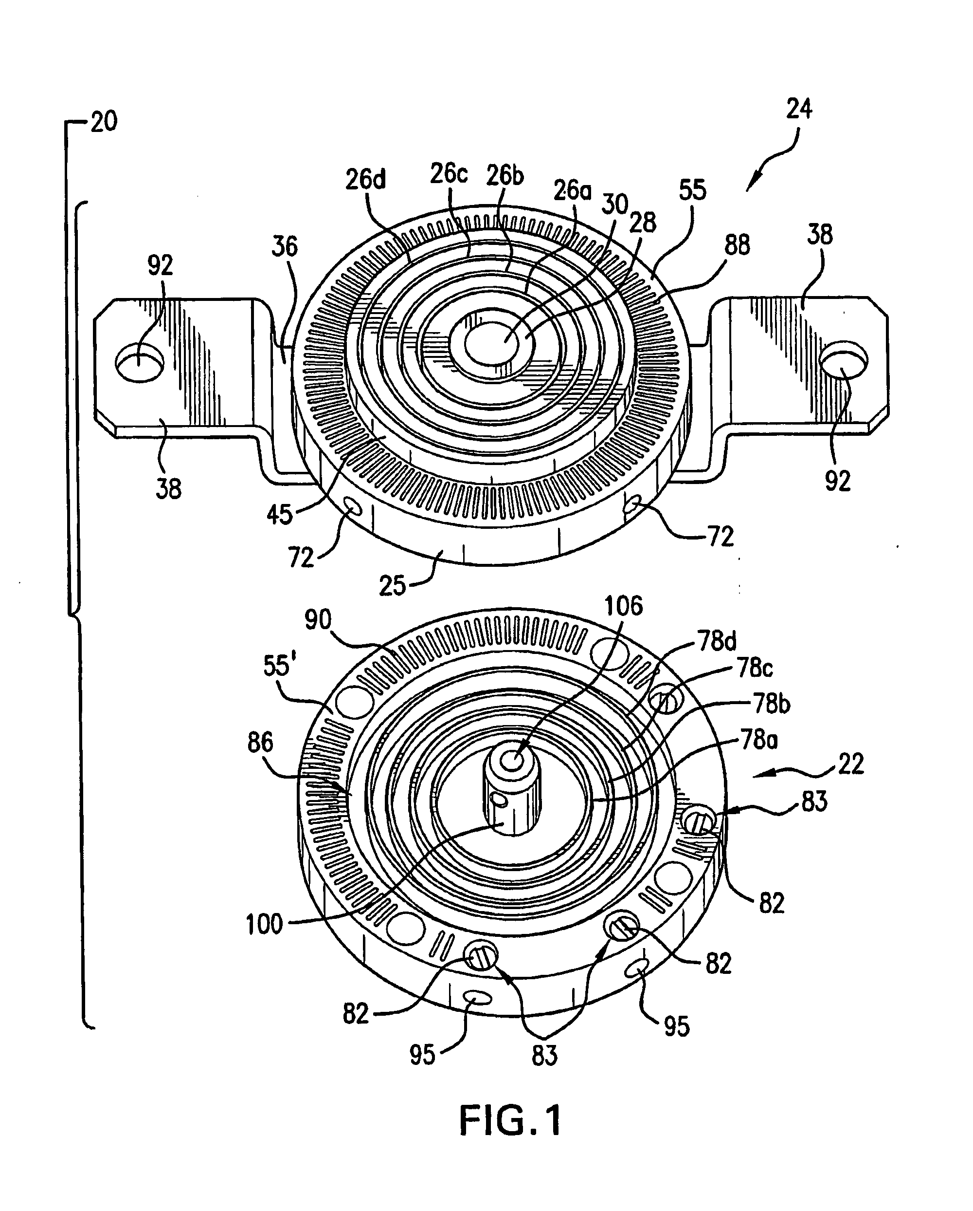
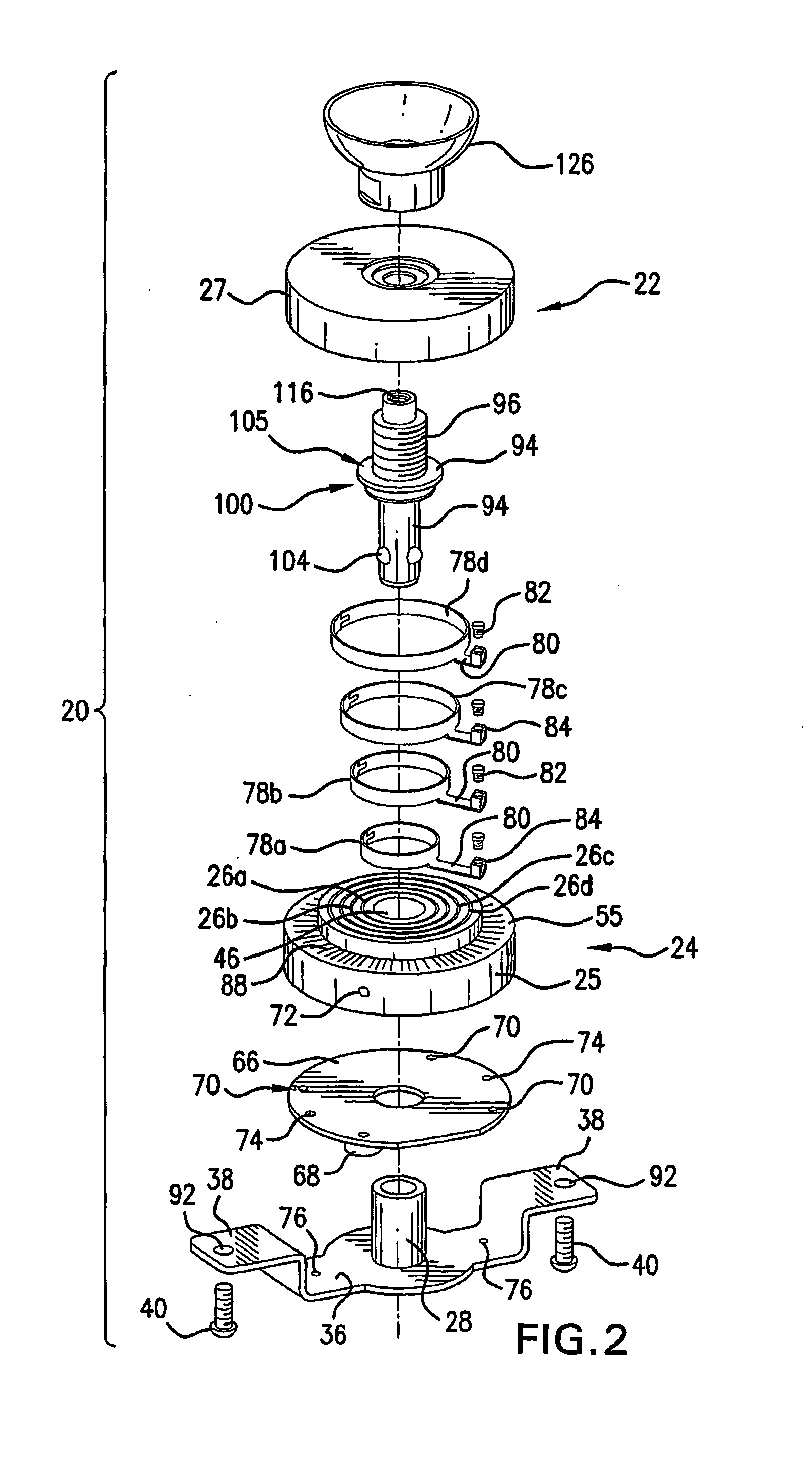
[0066]Referring first to FIGS. 1-4, a quick connect device 20 for installing electrical fixtures comprises the combination of a plug 22 and mating socket 24. The device 20 functions to both establish an electrical connection between an electrical fixture and electrical supply wiring, and mechanically support the fixture on a surface or base, typically a wall, ceiling or floor surface. As used herein, the term “fixture” or “electrical fixture” means any fixture or appliance such as a lighting fixture, ceiling fan, television camera, security device or any other device which is powered by electricity supplied by electrical wiring, and which requires a mechanical connection to support or suspend the fixture. Plug 22 is fixedly secured to an electrical fixture (not shown), while the socket 24 is secured to either the surface (e.g., wall, ceiling or floor) on which the fixture is to be mounted, or to an electrical junction box.

[0067]The socket 24 comprises a cylindrically shaped, essenti...


PUM


Abstract

A device for connecting and supporting fixtures, such as electrical fixtures, includes a male plug, a mating female socket and a releasable spindle assembly for both holding the plug in the socket and mechanically mounting the fixture on a supporting surface or an electrical box. The plug is provided with concentric, ring shaped male connectors that are matingly received within similarly shaped female recesses in the socket to create electrical connections and also allow the fixture to be rotated to any of a plurality or mounting orientations. The releasable spindle assembly is controlled by the actuation of a push rod operated by a tool or user's finger.

Description

TECHNICAL FIELD[0001]The present invention relates to electrical connectors and fixtures, and more particularly, to an electrical plug and socket combination allowing quick connection and mounting of electrical fixtures at electrical outlets.BACKGROUND ART[0002]Traditional techniques for installing electrical fixtures and appliances such as lighting fixtures and fans on walls or ceilings usually require the assistance of a qualified electrician, and the use of a variety of tools and specialized hardware. The procedure for installing or uninstalling such fixtures can also be relatively time consuming, even when performed by an experienced installer. In addition to the need for hand-wiring the necessary electrical connections between the fixture and electrical power supply wiring, the installer must make separate mechanical connections for supporting or suspending the fixture in place.[0003]One solution to the problem is disclosed in PCT Publication No. WO 0016442 (“PCT '442”). PCT '4...

Claims


Application Information

Patent Timeline
Patent Type & Authority Applications(United States)
IPC IPC(8): H01R13/60
CPCF21V21/002F21V21/02F21V23/06H01R2107/00H01R23/26H01R24/38H01R13/6276
Inventor KOHEN, RAN
Owner KOHEN RAN
Why Eureka
Try Eureka