Tubular filling system

a filling system and tubular technology, applied in the direction of sealing/packing, drilling pipes, wellbore/well accessories, etc., can solve the problems of time-consuming, if not impossible, inability to insert the seal into the tubular, and the seal is engaged in the tubular, so as to prevent erosion and facilitate connection or release

Inactive Publication Date: 2002-09-19
OFFSHORE ENERGY SERVICES
View PDF0 Cites 66 Cited by
  • Summary
  • Abstract
  • Description
  • Claims
  • Application Information

AI Technical Summary

Benefits of technology

0010] Another advantage of the present invention is to be able to handle sudden surges of pressure from the formation. In these situations, it is desirable to be able to secure a valve in the tubular string connected to the mud supply so that the pressure surge from the wellbore can be contained. Thus, an objective of the present invention is to allow rapid connection or release from a tubular being added or removed to or from a tubular string during insertion or removal operations.
0011] In addition it is another object of the present invention to provide an integral safety valve that is can be manually operated so as to shut-in the well and thereafter allows control of the well by applying fluid behind the valve. In addition an objective is to provide a safety valve that is not operated until required to assure its pressure holding integrity.
0012] It is yet another object of the present invention to allow a system of rapid connection and disconnection to the tubular for filling or capturing of returns with minimal or no spillage in the rig floor area.
0013] It is another object of the present invention to allow circulation of fluid at any time during rig operations for conditioning the wellbore, fluid system, or controlling a kick.
0014] It is another object of the present invention to provide a mud saver valve to prevent fluid from escaping the tool when the tool is disconnected from the tubular without having to operate the manually operated valve.
0015] In addition it is desirable to provide a very large flow path through the mud saver valve to prevent erosion. In addition it is also desirable to provide a large return flow path through the mud saver valve to allow fluid to flow from the tubular with little restriction.

Problems solved by technology

This is not desirable when a well kick occurs or fluid is overflowing from the tubular.
In the case where "side door" or latching elevators are used, the spacing of the seal system is very critical and the seal of previous devices must be engaged in the tubular prior to latching the elevators below the upset portion of the tubular.
When tubulars are racked back in the derrick such as multiple sections of drill pipe, it would be very time-consuming if not impossible to insert the seal into the tubular prior to latching the elevators.
There is a disadvantage in having the seal engaged in the tubular at all times that the elevators are latched.
If the open ended tubular is installed in a wellbore having fairly tight clearances with the tubular, rapid advancement of the tubular into the wellbore will result in significant flow of mud through the tubular and onto the rig floor area.
In addition when fluid is flowing from the tubular it is difficult to determine whether the flow is from decompression of the fluid column or flow from a formation in the well bore.
When attempting to pull the tubular from the wellbore, resistance to extraction can be experienced and consequently "swabbing in" and ultimate loss of control of the well could occur.
In some circumstances the outside of the tubular connection will become damaged due to tong marks of other damage caused by handling or normal wear while running the tubular in and out of the well that will prevent sealing on these surfaces.

Method used


Image

  • Tubular filling system
  • Tubular filling system
  • Tubular filling system

Examples


Embodiment Construction

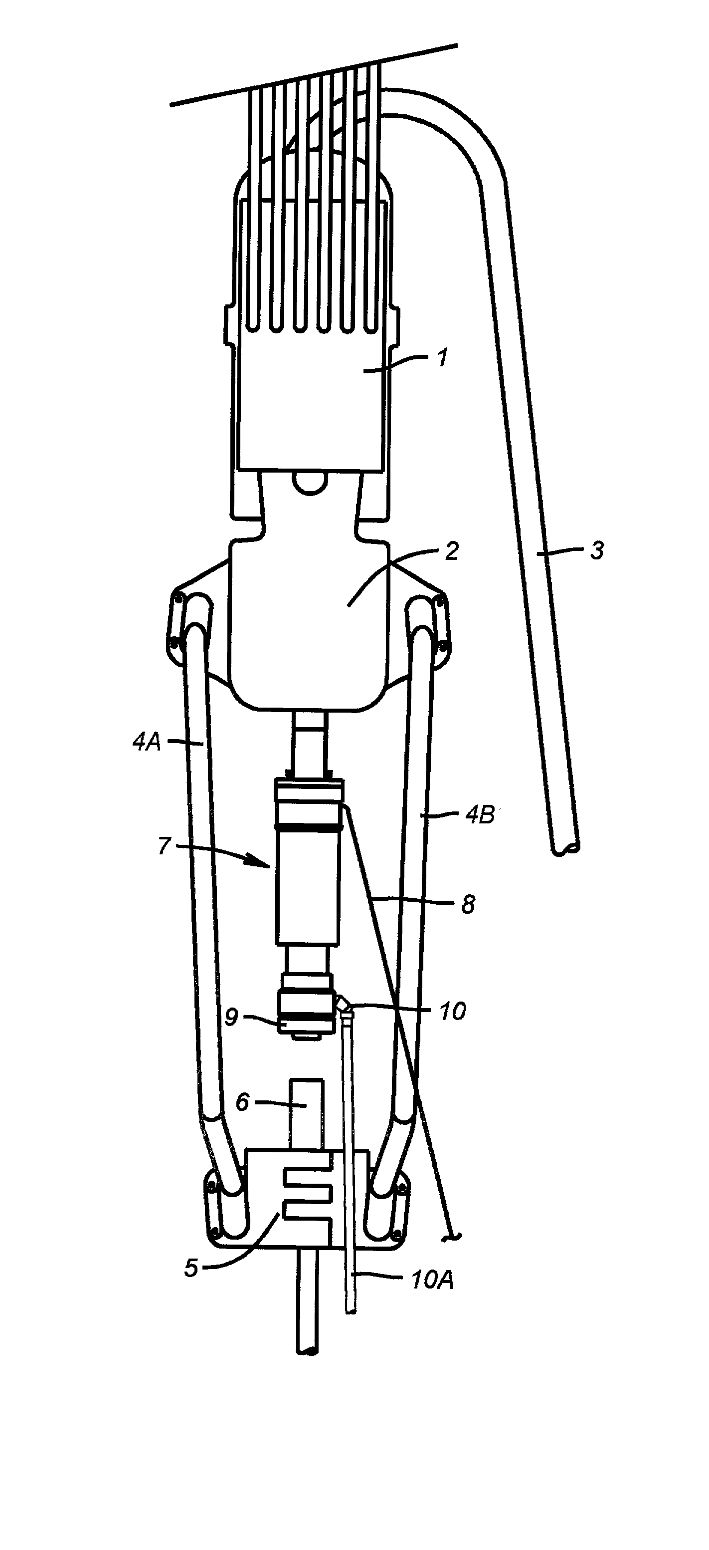
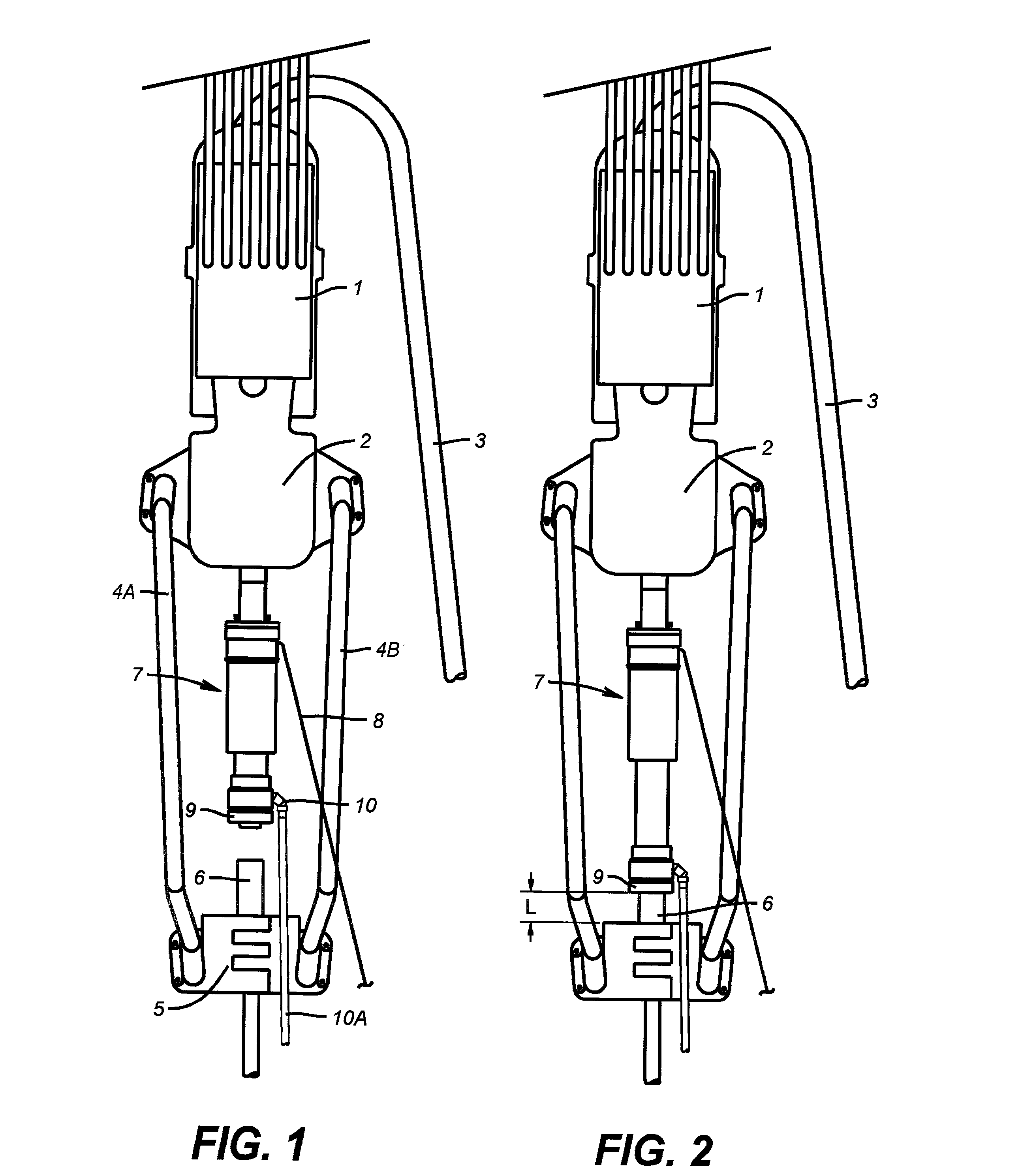
[0037] Referring now to FIG. 1, the invention (7) is shown connected to a top drive (2) which is hoisted by a traveling block (1). A mud line (3) is connected to the top drive and is connected to the mud system (not shown). A tubular (6) is shown being supported by an elevator (5) that is connected to the top drive by bails (4A and 4B). The tool (7) is shown in the retracted position with the seal unit (9) above the tubular (6). In this position it is easily understood that tubulars can be handled in a normal way. A single control line (8) is shown connected to the invention. A drain valve (10) is illustrated at the lower end of the extendable seal unit. A hose (10A) is shown attached to the drain valve (10). The operation of all of these elements will be explained in detail later.

[0038] Referring now to FIG. 2, the invention (7) is shown with the seal unit (9) extended and sealing on the tubular (6). In this position fluid can be pumped into or taken from the tubular through the to...


PUM


Abstract

A system for capturing displaced fluid or pumping fluid through tubulars being run into or out of the wellbore is described. Embodiments are supported by a traveling block and top drive unit with telescoping features to rapidly seal over a tubular to connect the tubular to a mud system. Alternative sealing arrangements for sealing inside the tubular connection are also disclosed. These alternate sealing arrangements also provide flow areas larger than the tubular body since no portion of these arrangements enter the tubular body. All of the sealing arrangements provide a biased area whereby any internal pressure in the invention forces the seals into more intimate contact with their mating seal surfaces. A mudsaver valve having a large flow capacity is described to keep fluid from spilling when the apparatus is removed from the tubular. This mudsaver valve also provides for pumping of fluid into the tubular or flow of fluid from the tubular to the mud system prior to removing the apparatus from the tubular. In these embodiments, the apparatus can be placed in threaded sealing contact with the tubular and can incorporate a safety valve that can be manually closed in the event of a well kick. In another embodiment, a singular control input accomplishes operation of the apparatus to extend or retract the telescoping feature. Also illustrated is a drain valve that provides a method of completely removing all fluid pressure from within the apparatus prior to removing the apparatus from the tubular. The drain system also provides a means of disposing of the excess fluid away from the rig floor where spillage is a danger to the personnel or environment. The drain system can also be connected to a scavenger system that is intended as a vacuum system for removal of spillage. Connection to this system eliminates all possible spillage and completely removes fluids from the tubular handling area.

Description

[0001] This application is a continuation in part of application 09 / 161,051 filed Sep. 25, 1998.FIELD OF THE INVENTION[0002] The field of this invention relates to an apparatus for filling or circulating fluids while inserting tubulars into or removing them from a wellbore and for recovery of fluids displaced when running tubulars into the wellbore. The field of this invention also relates to an apparatus for controlling a well.BACKGROUND OF THE INVENTION[0003] When tubulars are being run into or pulled from a wellbore, it is often necessary to fill the tubular, take returns from the tubular or circulate fluid through the tubular. This requires that the pipe be threaded to a circulation system or the use of a device for filling or circulating a wellbore. Previous devices for filling and circulating the wellbore are firmly attached to the traveling block or top drive. In either case a very precise spacing is required of the seal assembly relative to the tubular and elevators. In the ...

Claims


Application Information

Patent Timeline
Patent Type & Authority Applications(United States)
IPC IPC(8): E21B19/16E21B21/01E21B21/10E21B34/00E21B34/06
CPCE21B19/16E21B21/01E21B21/106E21B34/063E21B2034/005E21B2200/05
Inventor MULLINS, ALBERT AUGUSTUSVEGA, RAUL DANIEL
Owner OFFSHORE ENERGY SERVICES
Why Eureka
Try Eureka