Micro powered gas-forming device

a gas-forming device and micro-powered technology, applied in the direction of liquid materials, transportation and packaging, packaging goods types, etc., can solve the problems of high cost, battery depletion, and high cost of replacement, and achieve the effect of convenient portability of the gas-forming device, simple and economical manufacture, assembly and us

Inactive Publication Date: 2010-02-23
KIMBERLY-CLARK WORLDWIDE INC
View PDF70 Cites 21 Cited by
  • Summary
  • Abstract
  • Description
  • Claims
  • Application Information

AI Technical Summary

Benefits of technology

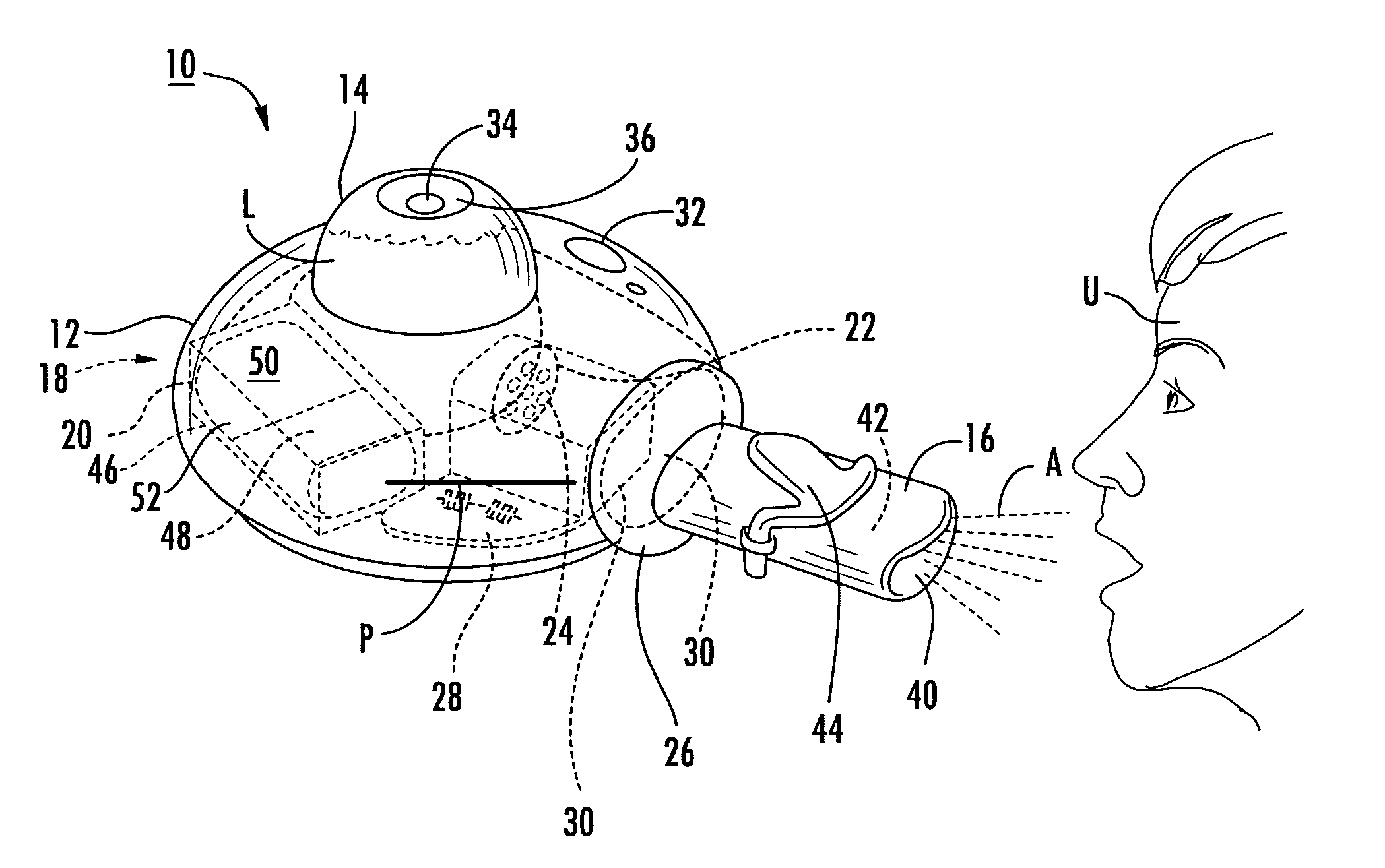
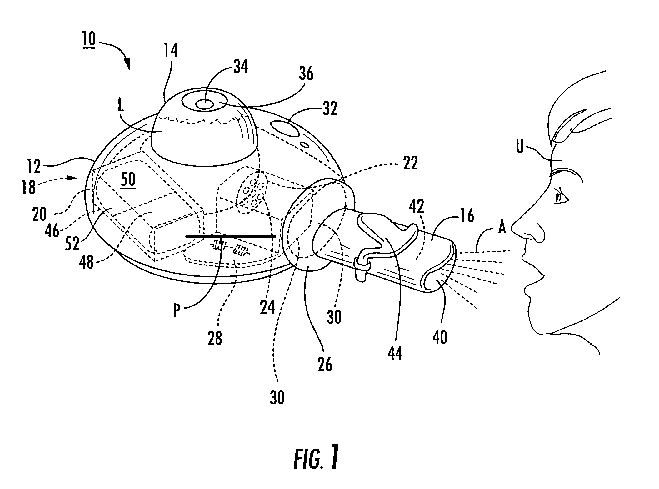
[0003]The present invention generally provides a micro powered gas-forming device such as a vaporizer and a steamer. A micro power source facilitates portability of the gas-forming device by eliminating electrical power cords in some embodiments and bulky motors in other embodiments while providing direct heat generation or electrical power in the gas-forming device with the energy being obtained from the reaction of a fuel with oxygen. The component parts of the micro powered gas-forming device are simple and economical to manufacture, assemble and use. Other advantages of the invention will be apparent from the following description and the attached drawings, or can be learned through practice of the invention.
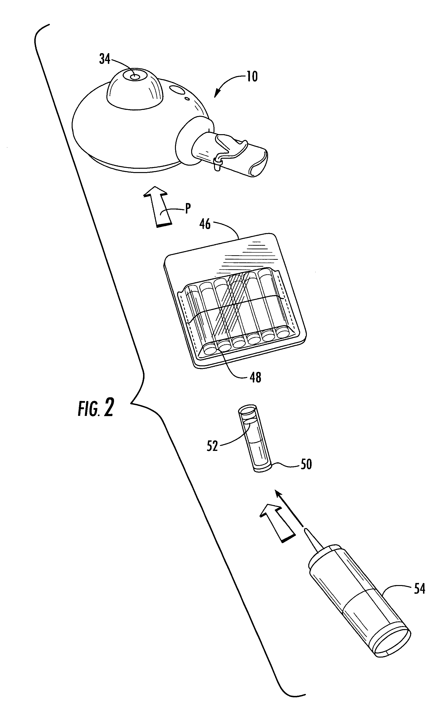
[0011]Further, the “micro power sources” according to various aspects of the present invention can be readily rechargeable by simply adding fuel to an empty fuel cartridge or replacing a spent fuel cartridge as will be described in detail in the following discussion.

Problems solved by technology

However, vaporizers and steamers using conventional power generation components such as batteries and electrical power cords suffer from a number of drawbacks.
If battery power is used, the batteries tend to deplete rapidly and must be replaced regularly, which over time becomes expensive.
If conventional electrical power is chosen, electrical cords prevent portability of the vaporizer or steamer.

Method used


Image

  • Micro powered gas-forming device
  • Micro powered gas-forming device
  • Micro powered gas-forming device

Examples


Embodiment Construction

[0067]Detailed reference will now be made to the drawings in which examples embodying the present invention are shown. The detailed description uses numerical and letter designations to refer to features of the drawings. Like or similar designations in the drawings and description have been used to refer to like or similar parts of the invention.

[0068]The drawings and detailed description provide a full and detailed written description of the invention and the manner and process of making and using it, so as to enable one skilled in the pertinent art to make and use it. The drawings and detailed description also provide the best mode of carrying out the invention. However, the examples set forth in the drawings and detailed description are provided by way of explanation of the invention and are not meant as limitations of the invention. The present invention thus includes any modifications and variations of the following examples as come within the scope of the appended claims and t...


PUM

PropertyMeasurementUnit
micro poweraaaaaaaaaa
poweraaaaaaaaaa
poweraaaaaaaaaa

Abstract

A gas dispenser includes a reservoir for holding a liquid, and a chamber in communication with the reservoir. The chamber receives the liquid, and a micro power source generates energy for conversion of the liquid disposed in the chamber. A nozzle defining an orifice in selective communication with the chamber. The nozzle is used to release the converted liquid from the chamber through the orifice.

Description

BACKGROUND OF THE INVENTION[0001]Consumers use a variety of devices to produce vapor and steam for breathing comfort and for cleaning purposes. Vaporizers, for instance, deliver vapor in low humidity environments to prevent dry skin and sinus passages and also to deliver therapeutic or medicinal ingredients such as menthol and pharmaceutical agents. Steamers provide steam for cleaning clothes, curtains and the like. However, vaporizers and steamers using conventional power generation components such as batteries and electrical power cords suffer from a number of drawbacks. If battery power is used, the batteries tend to deplete rapidly and must be replaced regularly, which over time becomes expensive. If conventional electrical power is chosen, electrical cords prevent portability of the vaporizer or steamer.[0002]A device is needed in the industry, which utilizes a compact, portable power source that enables a user to transport the vaporizer or steamer in a purse, pocket, suitcase ...

Claims


Application Information

Patent Timeline
Patent Type & Authority Patents(United States)
IPC IPC(8): A61M11/00
CPCA61M11/041A61M2205/8268A61M11/042A61M11/065
Inventor LINDSAY, JEFFREY D.CHEN, FUNG-JOURIPPL, CARL G.TYRRELL, DAVID J.ELLEFSON, KIMMEYER, MARY JO
Owner KIMBERLY-CLARK WORLDWIDE INC
Why Eureka
Try Eureka