Portable wound treatment apparatus having pressure feedback capabilities

a portable, wound treatment technology, applied in the field of wound healing, can solve the problems of patient treatment on the apparatus for a long time, limit its use, etc., and achieve the effects of easy replacement, reduced pressure, and convenient removal and replacemen

Inactive Publication Date: 2010-03-02
KCI LICENSING INC
View PDF159 Cites 206 Cited by
  • Summary
  • Abstract
  • Description
  • Claims
  • Application Information

AI Technical Summary

Benefits of technology

[0008]The canister should be removably mounted within the housing, e.g. by means of a latch or similar release mechanism, so that the canister can be readily removed and replaced when full.
[0009]In a portable therapeutic apparatus (in contrast with a static apparatus of the kind described in the above PCT application which cannot be easily carried by the patient), it is less easy to determine the pressure prevailing at the wound site being treated. This is because the pressure will depend, in part, upon the hydrostatic height between the pump and the wound being treated and this height may vary during the treatment, depending upon the patient's movements. Apparatus in accordance with the invention overcomes this problem by providing an additional conduit connecting the wound site or an area close thereto to a pressure-detecting means, preferably located in the housing. The pressure-detecting means can be linked to a microprocessor programmed to maintain such pressure within a predetermined range irrespective of the movement of the patient. This can be done by, for example, signaling the pump to increase its speed where the hydrostatic pressure increases between the pump and the wound site or, conversely, reducing its speed where the hydrostatic pressure is reduced. This feature can also be used in a static therapeutic apparatus of the kind described in the abovementioned PCT application.
[0011]Thus, when the liquid reaches a level within the canister so as to substantially occlude the filter, a sharp pressure change occurs in the conduit between the canister and the pump. By monitoring this pressure change, the point at which the canister is filled can be accurately determined.

Problems solved by technology

The apparatus described in the above application has proved to be clinically effective but there are some limitations in its use.
However, it may require the patient to undergo treatment on the apparatus for a long period.

Method used


Image

  • Portable wound treatment apparatus having pressure feedback capabilities
  • Portable wound treatment apparatus having pressure feedback capabilities
  • Portable wound treatment apparatus having pressure feedback capabilities

Examples


Embodiment Construction

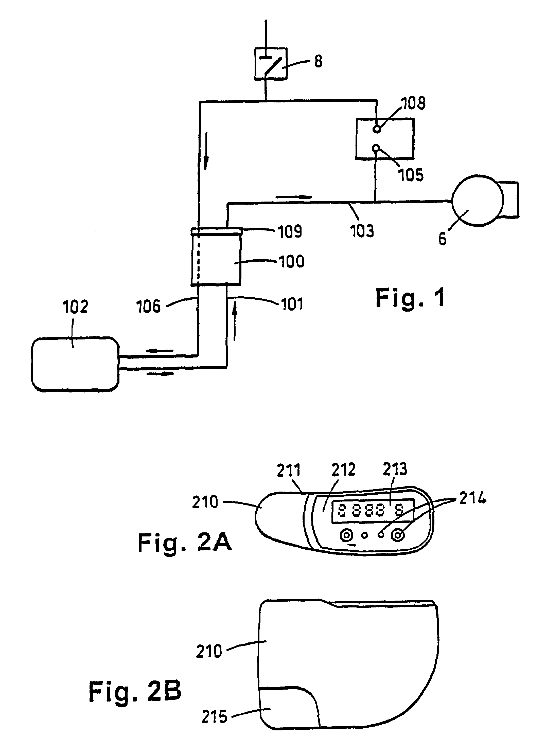
[0023]Referring to the drawings, the portable therapeutic apparatus comprises a housing 210 (best shown in FIGS. 2A and 2B), having rounded corners and a side 211 which is concavely curved in order to fit comfortably to the wearer's body.

[0024]The shaping of the housing with curved surfaces is to avoid sharp corners or edges which could dig in to the user or his career. The upper surface 212 is generally flat and has an LCD screen 213 on which details such as applied pressure can be displayed. Control buttons 214 are provided to adjust pressures and treatment intervals. Provision is made for housing a canister within the housing and a snap release cover 215 is arranged for removing or introducing the canister.

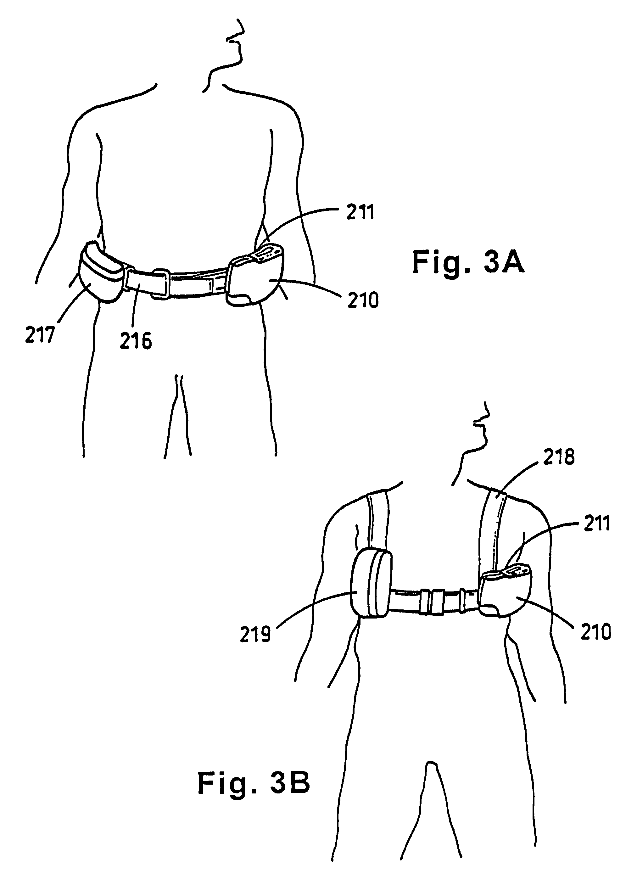
[0025]FIGS. 3A and 3B show schematically ways in which the housing 210 may be supported on the patient's body. In FIG. 3A the housing 210 is supported on a belt 216 and its weight is balanced by a similarly rounded casing 217 containing a rechargeable battery pack. FIG. 3B show...


PUM


Abstract

A reduced pressure treatment apparatus includes a drape for positioning over the wound site to create and maintain a substantially air-tight cavity between the wound site and the drape. A multi-lumen suction tube is provided to be attached to a reduced pressure source. The multi-lumen suction tube includes a center lumen and at least one outer lumen and is configured to deliver reduced pressure beneath the drape to the substantially air-tight cavity. The multi-lumen suction tube is adapted to allow fluid to be drawn from the wound site through the center lumen and pressure to be monitored at the wound site through the at least one outer lumen.

Description

CROSS-REFERENCE TO RELATED APPLICATION[0001]This application is a continuation application of U.S. patent application Ser. No. 09 / 613,497, filed Jul. 11, 2000, which is a continuation of U.S. patent application Ser. No. 09 / 078,223, filed May 13, 1998, now U.S. Pat. No. 6,142,982, which is a continuation of International Application No. PCT / GB96 / 02802, filed Nov. 14, 1996, which claims priority to British Patent Application No. GB9523253.4, filed Nov. 14, 1995. All of the above-mentioned patents and applications are hereby incorporated by reference in their entirety.BACKGROUND OF THE INVENTION[0002]This invention relates to the healing of wounds and, more particularly, to apparatus for stimulating the healing of superficial wounds.[0003]PCT Application No. GB95 / 01983 (WO 96 / 05873) describes apparatus for stimulating the healing of wounds comprising a porous pad which is permeable to fluids for introduction into the wound, a dressing for covering the wound and providing an air-tight s...

Claims


Application Information

Patent Timeline
Patent Type & Authority Patents(United States)
IPC IPC(8): A61M1/00A61F13/00A61M27/00
CPCA61M1/0023A61M1/0052A61M1/0088A61M27/00A61M1/0049A61M1/0056A61M2205/15A61M2205/18A61M2205/3344A61M2205/3351A61M2205/3379A61M2205/581A61M2205/583A61M2205/8206A61M2209/088Y10S604/902A61M1/0037A61M1/75A61M1/784A61M1/78A61M1/79A61M1/80A61M1/984A61M1/982A61M1/82A61M1/915A61M1/732A61M1/96
Inventor HUNT, KENNETH WILLIAMHEATON, KEITH PATRICK
Owner KCI LICENSING INC
Why Eureka
Try Eureka