Apparatus for priming microfluidics devices with feedback control

a microfluidics and apparatus technology, applied in the field of microfluidics, can solve the problems of affecting the detection sensitivity of the instrument, affecting the uniformity of different chips, and being particularly susceptible to dye binding, so as to improve the efficiency and efficiency of the priming unit, and be easily removed and replaced.

Active Publication Date: 2006-07-27
CAPLIPER LIFE SCI INC +1
View PDF24 Cites 25 Cited by
  • Summary
  • Abstract
  • Description
  • Claims
  • Application Information

AI Technical Summary

Benefits of technology

[0009] The present invention resides in a priming unit for a microfluidics device, the priming unit containing a pressurization unit, a pressure detector, and preferably a temperature detector as well, plus a feedback loop to receive signals from the detector(s) and process the signals to provide a pressure vs. time profile that will result in full priming of the microfluidics device based on the viscosity characteristics of the priming fluid, without excess exposure time. In preferred embodiments of the invention, specialized features of construction contribute further to the economy and efficiency of the priming unit. One example of such a feature is a barrel and motorized plunger to apply air pressure to the reservoirs that contain the priming fluid and feed the microchannels. Another is the combination of the barrel, a mount for the plunger motor, and a mount for the pressure detector in a single piece, such as an injection molded part. Still another is an innovative seal at the site where the piston barrel contacts a reservoir in the carrier, that can be readily removed and replaced when worn. These and other features, objects and advantages of the invention and its use will be apparent from the description that follows.

Problems solved by technology

Wall- bound dye in the detection channel becomes background signal that adversely affects the detection sensitivity of the instrument and causes nonuniformity between different chips.
Chips intended for use with matrices containing RNA, for example, are particularly susceptible to dye binding due to the cationic nature of the RNA dye.

Method used


Image

  • Apparatus for priming microfluidics devices with feedback control
  • Apparatus for priming microfluidics devices with feedback control
  • Apparatus for priming microfluidics devices with feedback control

Examples


Embodiment Construction

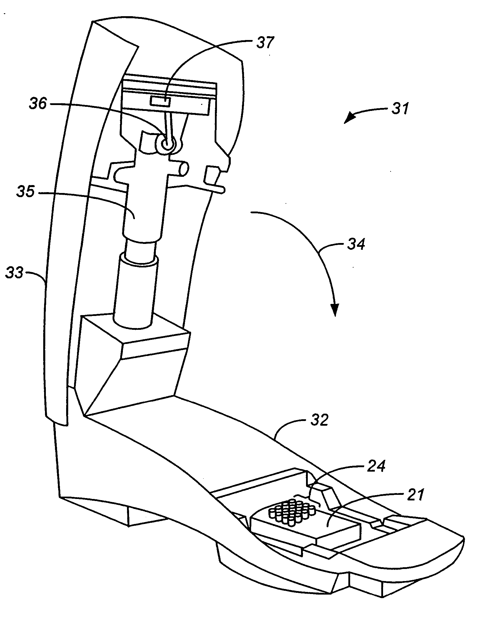
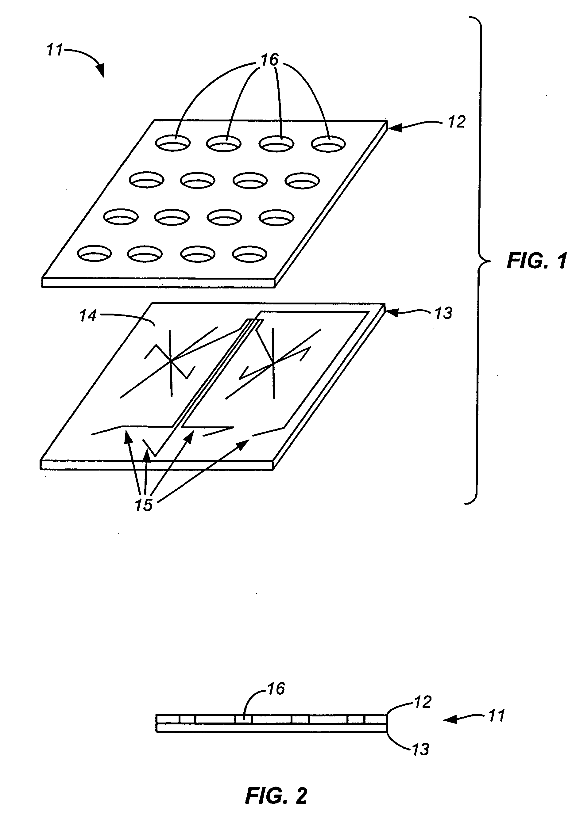
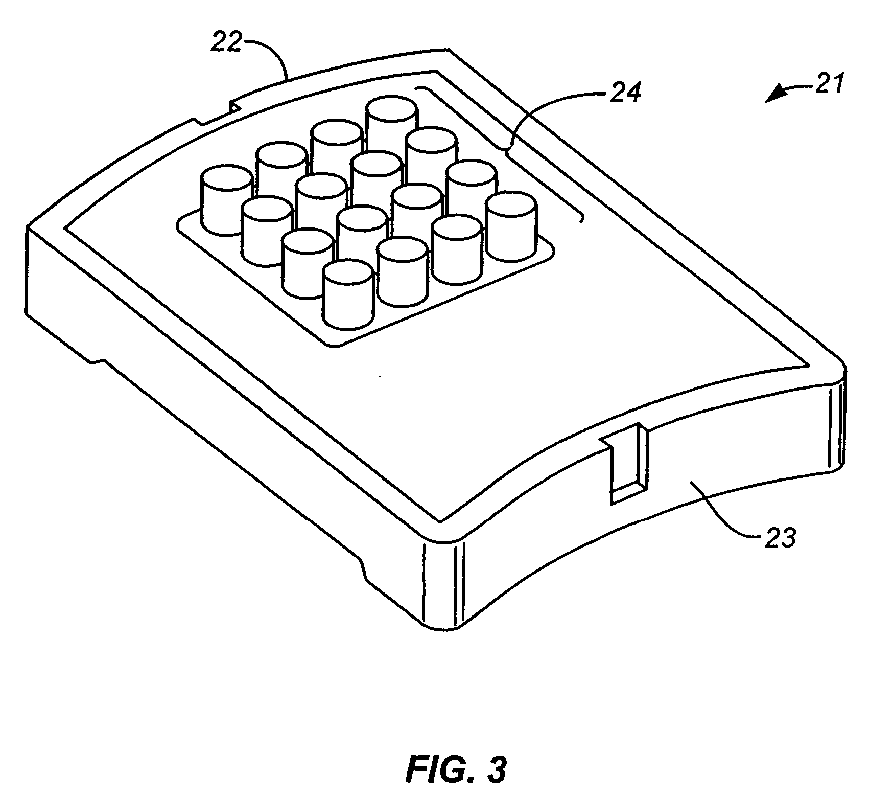
[0016] While the invention is susceptible to a wide range of configurations and embodiments, the underlying concepts and principles of the invention and its novel aspects can be understood by a detailed review of a specific embodiment. One such embodiment is depicted in FIGS. 4, 5, and 6 and described below.

[0017] The priming unit 31 of FIG. 4 includes a base 32 and a top 33, joined by a hinge connection at the rear of the base. The unit is shown in an open position, and is closed by rotating the top down in the direction of the arrow 34. To prepare the unit for priming of a microfluidics device, one or more of the reservoirs of the carrier holding the microfluidics device is filled with the priming fluid, whether the fluid be a gel or liquid. This can be done by pipette either before or after the carrier has been placed inside the priming unit but before the priming unit has been closed over the carrier. Once the priming unit is closed, the supply lines in the priming unit are eng...


PUM

PropertyMeasurementUnit
temperatureaaaaaaaaaa
pressureaaaaaaaaaa
pressureaaaaaaaaaa

Abstract

A priming unit for a microfluidics device contains a pressurization unit and pressure and temperature detectors as part of a feedback loop that controls the pressure applied by the pressurization unit and the time during which the pressure is applied. This control feature is particularly useful in controlling the exposure time of the microchannels to dyes in the priming liquids since certain dyes tend to adhere to the walls of the channels and produce non-uniform results.

Description

CROSS REFERENCE TO RELATED APPLICATION [0001] This application claims benefit from U.S. Provisional Patent Application No. 60 / 635,223, filed Dec. 10, 2004, the contents of which are incorporated herein by reference in their entirety.BACKGROUND OF THE INVENTION [0002] 1. Field of the Invention [0003] This invention resides in the field of microfluidics, and in particular to certain features of an automated priming unit designed to fill the channels of a microfluidics device with liquids or gels. The invention is of particular interest to “lab-on-a-chip” systems for automated electrophoresis. [0004] 2. Description of the Prior Art [0005] Electrophoresis is one example of a laboratory procedure that can be performed in an automated manner in a microfluidics device. Other examples are micro-scale binding assays and simulations of various processes and phenomena such as fluid dynamics, structural dynamics, thermal dynamics, and reaction kinetics. As a representative example, electrophore...

Claims


Application Information

Patent Timeline
Patent Type & Authority Applications(United States)
IPC IPC(8): G01N27/447
CPCB01L3/0293B01L3/5027B01L9/527B01L2200/146Y10T436/25G01N27/44743G01N27/44756Y10T436/11Y10T436/2575B01L2400/0487
Inventor BORONKAY, ALLENKENNEDY, COLINLATHAM, MATTHEW
Owner CAPLIPER LIFE SCI INC
Why Eureka
Try Eureka