
Connector for domed cutting tool

a technology of connecting rods and cutting tools, applied in the field of surgical devices, can solve the problems of reducing cutting accuracy, discarded entire milling tools, and high manufacturing costs of devices, and achieves the effects of reducing manufacturing costs, superior cutting edges, and reducing cutting accuracy

Inactive Publication Date: 2009-09-15
VIANT AS&O HLDG LLC
View PDF18 Cites 31 Cited by
  • Summary
  • Abstract
  • Description
  • Claims
  • Application Information

AI Technical Summary

Benefits of technology

[0010]Briefly, and in general terms, the present invention provides for an improved reaming tool that is fabricated from machined metal components to provide greater cutting accuracy, and at lower manufacturing costs than conventional cutters. The reaming tool has a multiplicity of cutters that can be formed of heat treated tool steel, to provide superior cutting edges. In addition, once the individual cutters become dull, they can readily be removed, replaced, and can even be resharpened and used again, for improved economy of use and maintenance.

Problems solved by technology

The outer wall of the milling tool forming the cup-shaped cutting edge projections is relatively thin, resulting in reduced cutting accuracy.
Typically, if the cutting surfaces are formed integrally with the shell, such as with raised cutting edges formed directly in the shell, the manufacturing of the devices becomes very costly.
In addition, once the projections forming the cutting edges of the milling tool are dull, the entire milling tool is typically discarded.

Method used


Image

  • Connector for domed cutting tool
  • Connector for domed cutting tool
  • Connector for domed cutting tool

Examples


Embodiment Construction

)

[0055]During surgery for preparation of a joint for installation of a joint prosthesis, it has become important to capture and preserve the tissue and debris removed from a joint for later use. However, conventional surgical tools with hollow cutting heads that are typically used for this type of surgery commonly have cup-shaped cutting edge projections that are relatively thin, become dull relatively rapidly during use, and are not readily sharpened or replaced, so that once the cutting edges of the surgical tool become dull, the surgical tool is useless.

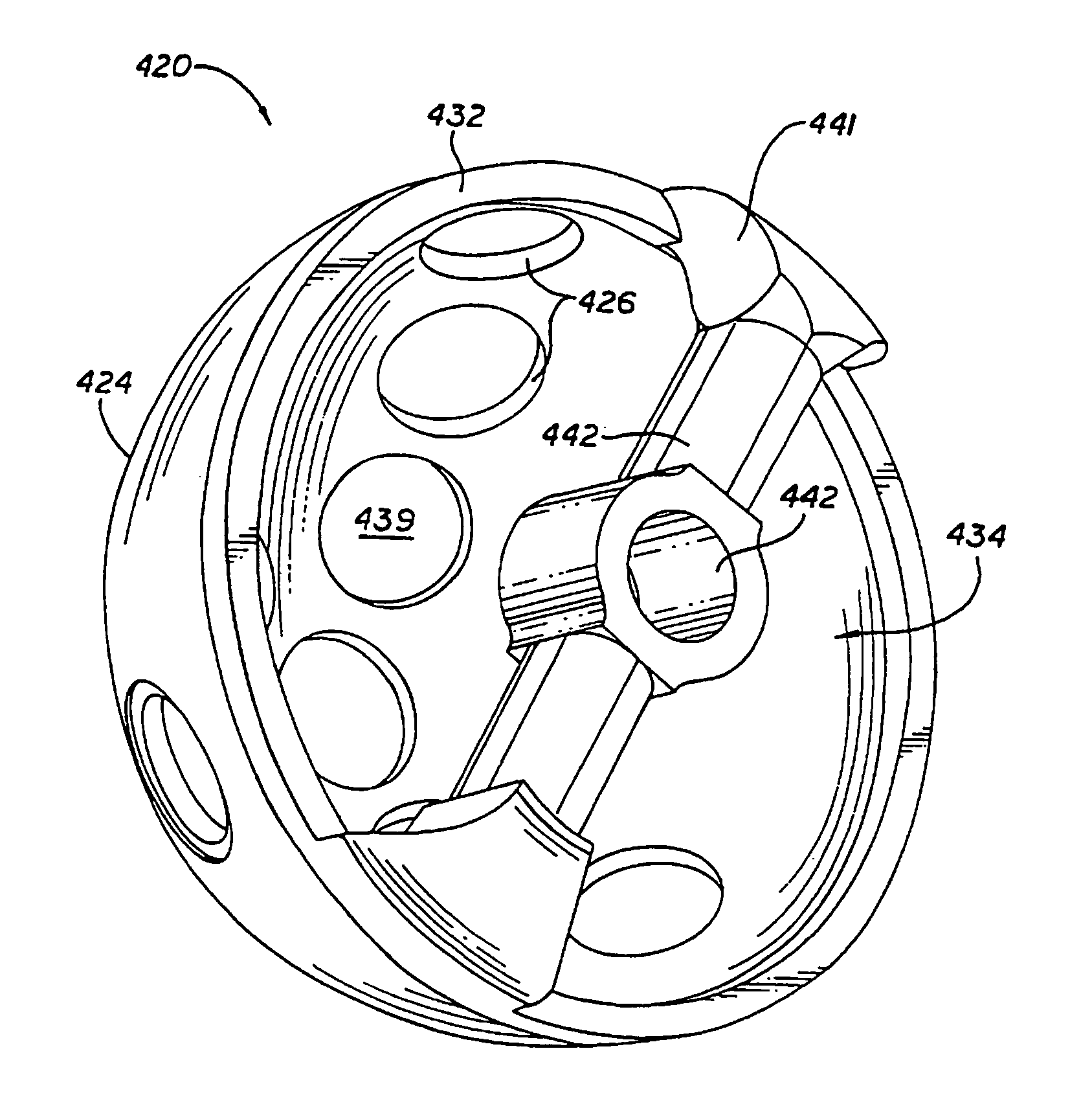
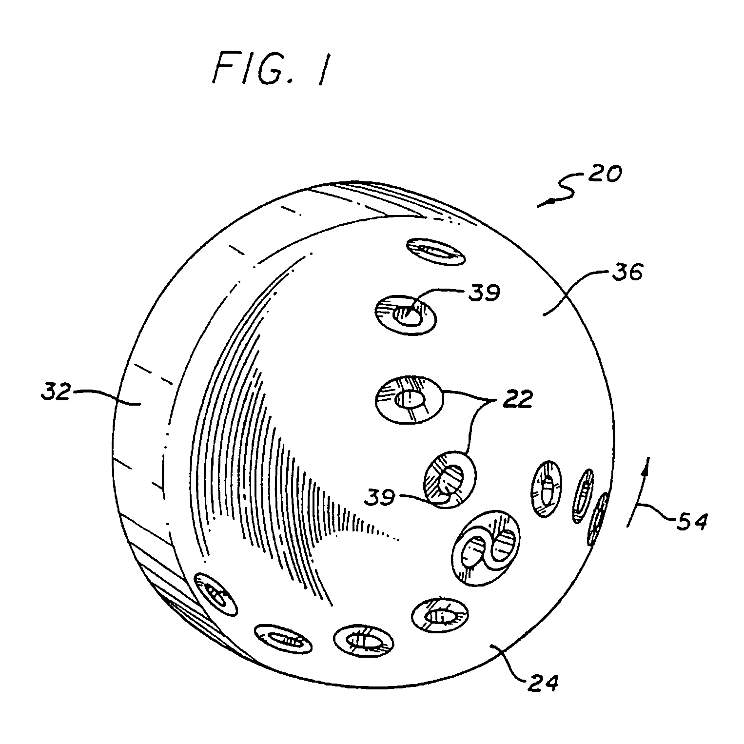
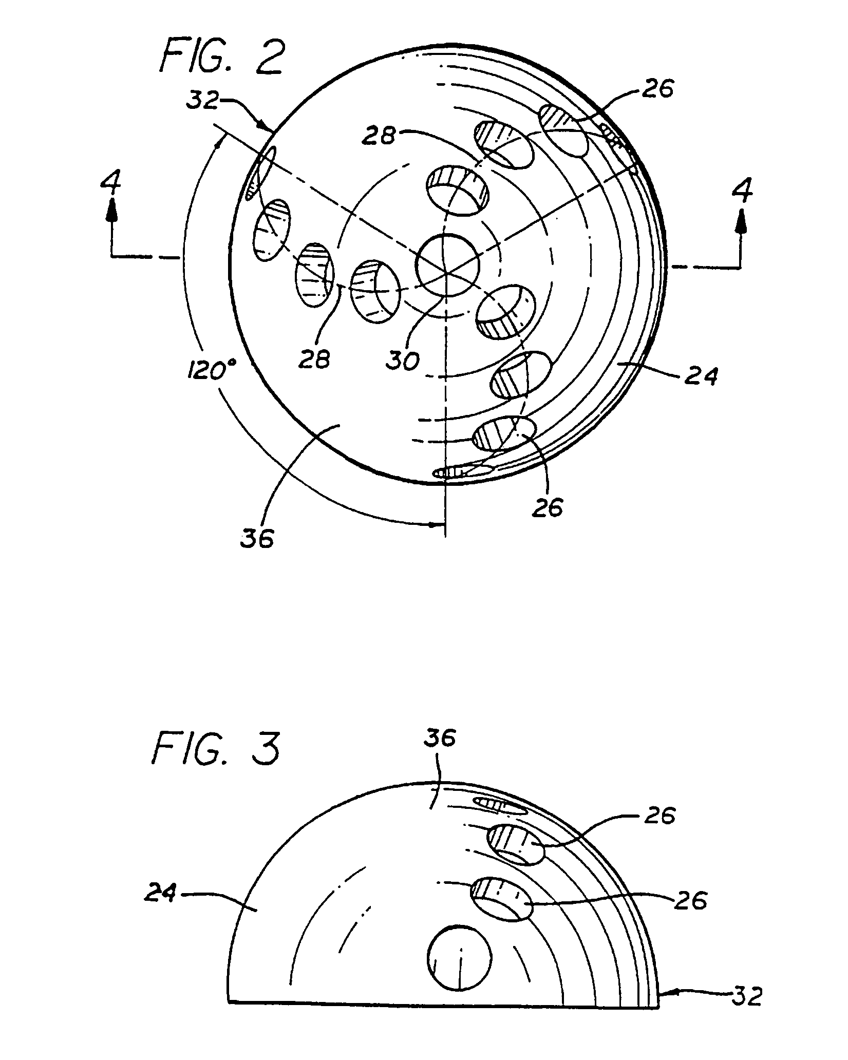
[0056]As is illustrated in the drawings, the invention is accordingly embodied in a hollow dome reamer that provides greater cutting accuracy, with removable teeth having superior cutting edges. The removable teeth can readily be replaced, and resharpened for repeated usage. Referring to FIGS. 1 through 11, the hollow dome reamer 20 is preferably a rotary surgical reamer having a plurality of inserted modular teeth 22 or cutters t...


PUM


Abstract

The surgical reamer has a hollow dome with apertures spaced apart arranged in arcs extending from an apex of the dome to the base portion of the dome, and removable teeth positioned in the apertures. Each cutting tooth has a flange that is aligned flush with the external surface of the dome, and a raised cutting edge extending above the flange and the external surface of the dome, and an interior passageway communicating between the outside and inside of the dome. In one embodiment, a base plate is removably secured on the base portion of the dome to provide closure of the central cavity of the dome.

Description

CROSS REFERENCE TO RELATED APPLICATIONS[0001]This application is a continuation of U.S. patent application Ser. No. 10 / 359,605, filed Feb. 7, 2003, now U.S. Pat. No. 7,048,740, which is a continuation of U.S. patent application Ser. No. 09 / 671,234, filed Sep. 19, 2000, now abandoned, which is the U.S. national stage of international patent application No. PCT / US99 / 05951, filed Mar. 18, 1999, which claims priority to U.S. patent application Ser. No. 09 / 040,861, filed Mar. 18, 1998, now U.S. Pat. No. 5,976,144.TECHNICAL FIELD[0002]This invention relates generally to surgical devices, and more particularly concerns a rotatable surgical cutting tool for shaping a joint socket in preparation for receiving a joint prosthetic device.BACKGROUND OF THE INVENTION[0003]It is now common practice in the treatment of severe cases of arthritic and other forms of degenerative joint diseases, especially the hip, to shape the hip joint socket by removing diseased and eroded bone and cartilage to conf...

Claims


Application Information

Patent Timeline
Patent Type & Authority Patents(United States)
IPC IPC(8): A61B17/00
CPCA61B17/1666A61B17/1684A61B2017/00473
Inventor WHITE, PATRICK M.FISHBEIN, MEYER
Owner VIANT AS&O HLDG LLC
Learn More